4. Configuration
118
Data Range: is a read-only field and reports on the range of addresses that is being used by this
mapping. It is formed by the sum of the fields "Initial Address" and "Size". There can be no range
overlays with others mappings of the same "data type".
ATTENTION:
Unlike other tasks of an application, when a mark is reached at MainTask debugging, the MODBUS
Ethernet Server instance task or any other MODBUS task will stop being executed at the moment it
tries to write in the memory area. This occurs in order to maintain data consistency of memory areas
while MainTask is not running.
MODBUS Server Ethernet Protocol Configuration via Direct Representation (%Q)
To configure this protocol using Direct Representation (%Q), the user must perform the following
steps:
Configure the general parameters of MODBUS Server Protocol, such as: communication times,
address and direct representation variables (%Q) to receive the diagnostics and control relation.
Add and configure MODBUS relations, specifying the MODBUS data type, direct representation
variables (%Q) to receive/write the data and amount of data to be reported.
The descriptions of each configuration are listed below in this chapter.
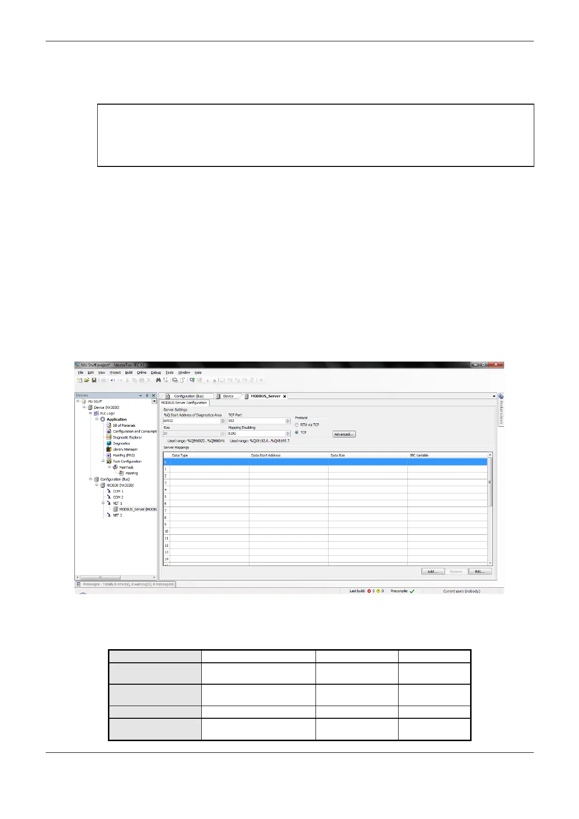
General Parameters of MODBUS Server Protocol – Configuration via Direct Representation (%Q)
The general parameters, found on the home screen of MODBUS protocol configuration (Figure
4-40), are defined below.
Figure 4-40. MODBUS Server Setup Screen
TCP port, protocol and direct representation variables (%Q) to control relations and diagnostics:
%Q Start Address of
Diagnostics Area
Starting address of the
diagnostic variables
Starting address used to
disable MODBUS relations
 Loading...