4. Configuration
119
Table 4-83. Settings to control relations and diagnostics
Notes:
%Q Start Address of Diagnostics Area: this field is limited by the size of output variables
addressable memory (%Q) at CPU, which can be found in chapter Technical Description - Specific
Features.
TCP Port: if there are multiple instances of the protocol added in a single Ethernet interface,
different TCP ports must be selected for each instance. Some TCP ports, among the possibilities
mentioned above, are reserved and therefore cannot be used. They are: 80, 8080, 1217, 1740, 1741,
1742.1743 and 11740.
Mapping Disabling: composed of 32 bits, used to disable, individually, the 32 MODBUS relations
configured in Server mappings space. The relation is disabled when the corresponding bit is equal to
1, otherwise, the mapping is enabled.
Default Value: the factory default value cannot be set to the Initial Address of Diagnostics in %Q
field, because the creation of a Protocol instance may be held at any time on application
development. The MasterTool IEC XE software itself allocate a value, from the range of output
variables of direct representation (%Q), not used yet.
The communication times of the MODBUS Server protocol, found on the "Advanced ..." button of
the configuration screen, are divided into: Task Cycle (ms) and Connection Downtime Time-out (s).
Further details are described in MODBUS Server Protocol General Parameters – Configuration via
Symbolic Mapping section.
The diagnostics and MODBUS commands are described in Table 4-81.
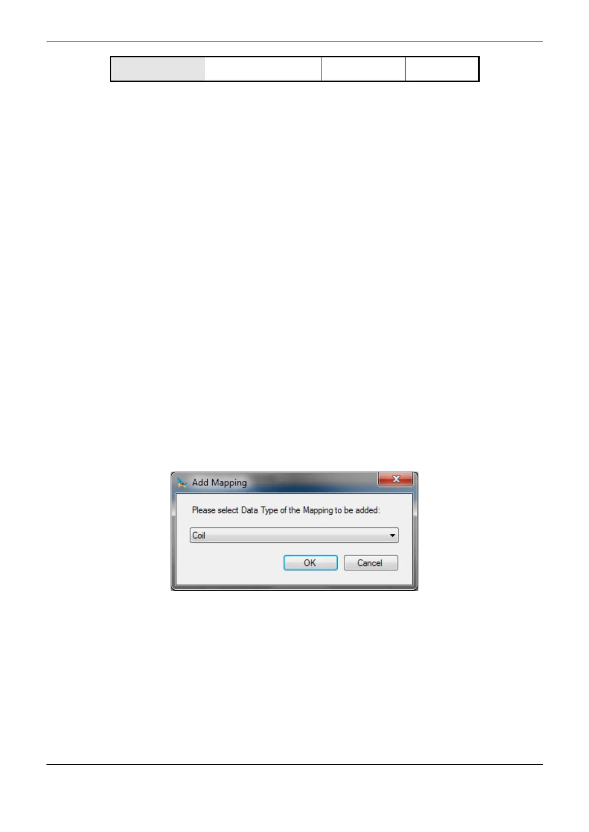
Mapping Configuration – Configuration via Direct Representation (%Q)
The MODBUS relation configuration, depicted on Figure 4-41 and Figure 4-42, follow the
parameters described on Table 4-84:
Figure 4-41. MODBUS Data Type
 Loading...