4. Configuration
120
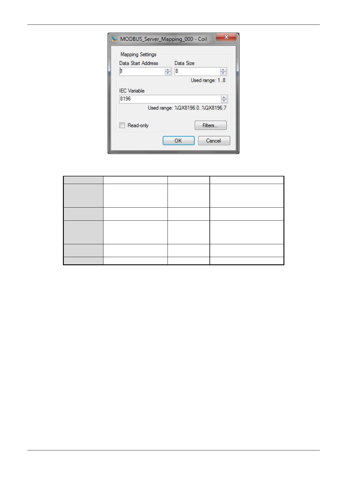
Figure 4-42. MODBUS Function
Coil (1 bit)
Holding Register (16 bits)
Input Status (1 bit)
Input Register (16 bits)
MODBUS data initial
address
1 to 65536 (Holding Register
and Input Register)
8 to 65536 (Coil and Input
Status)
Variables initial address
(%Q)
Table 4-84. Server Mappings
Notes:
Options: the values written in the column Options may vary according with the configured
MODBUS data.
Data Size: the Data Size value sets the maximum amount of data that a MODBUS relation can
access from the initial address. Thus, to read a continuous range of addresses, it is necessary that all
addresses are declared in a single relation. This field varies according to the set MODBUS data type,
that is, when selected Coil or Input Status, the field data size must be a number multiple of 8. It is
also important to take care so the maximum value is not greater than the addressable output memory
size and the attributed values aren’t the same already used during the application.
IEC Variable: in case the MODBUS data type is Coil or Input Status (bit), the IEC variables initial
address will be in the format for example %Q10X.1. However, if the MODBUS data type is Holding
Register or Input Register (16 bits), the IEC variables initial address will be in the format %QW. This
field is limited by the memory size of the addressable output variables (%Q) from each CPU, which
can be seen on the Technical Description - Specific Features chapter.
Read-only: when enabled, it only allows the communication master to read the variable data. It does
not allow the writing. This option is valid for the writing functions only.
Default: the default cannot be defined for the IEC Variable field as the creation of a protocol
instance can be made at any moment within the applicative development, making the MasterTool
IEC XE software allocate a value itself from the direct representation output variables range (%Q)
 Loading...