4. Configuration
158
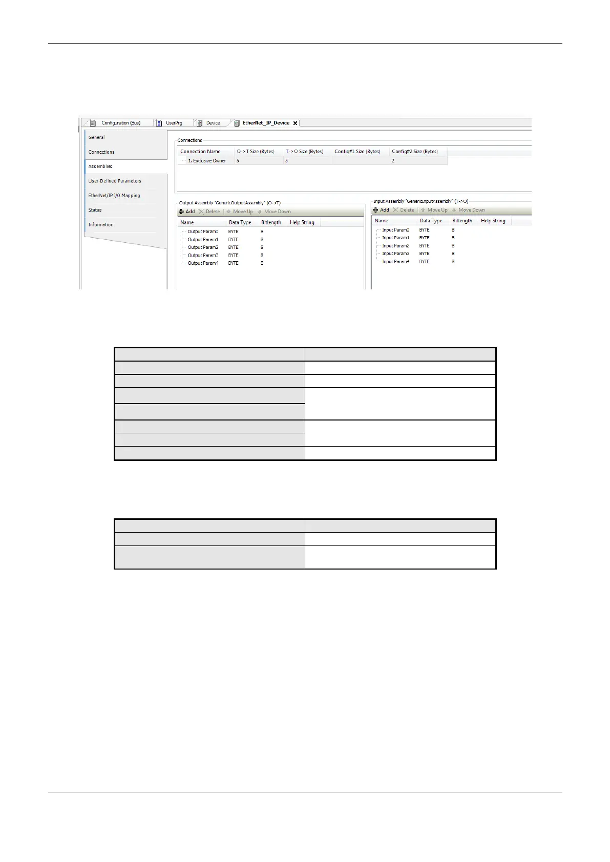
Assemblies
The upper area of the Assemblies tab displays a list of all configured connections. When a
connection is selected, the associated inputs and outputs are displayed in the lower area of the tab.
Figure 4-67. EtherNet/IP Assemblies
Output Assembly and Input Assembly:
Opens the dialog box “Add Input/Output”.
Deletes all selected Inputs/Outputs.
Moves the selected Input/Output within the list.
The order in the list determines the order in the
I/O mapping.
These values can be changed by double-clicking
into the text field.
This value must not be edited.
Table 4-99. EtherNet/IP Assemblies tab
Dialog box “Add Input/Output”:
Name of the input/output to be inserted,
Type of the input/output to be inserted. This type
also define its bitlength
Table 4-100. EtherNet/IP “Add Input/Output” window
EtherNet/IP I/O Mapping
I/O Mapping tab shows the name of the automatically generated instance of the Adapter under IEC
Objects in the Variable column. In this way, the instance can be accessed by the application. Here the
project variables are mapped to adapter’s inputs and outputs.
The “Always update variables” option must be keeped as default in “Enable 1”.
EtherNet/IP Adapter Configuration
The EtherNet/IP Adapter requires Ethernet/IP Modules. The Modules will provide I/O mappings that
can be manipulated by user application through %I or %Q addresses according to its configuration
(INPUT BYTE, OUTPUT BYTE, etc).
 Loading...