4. Configuration
88
Devices Configuration – Configuration for Direct Representation (%Q)
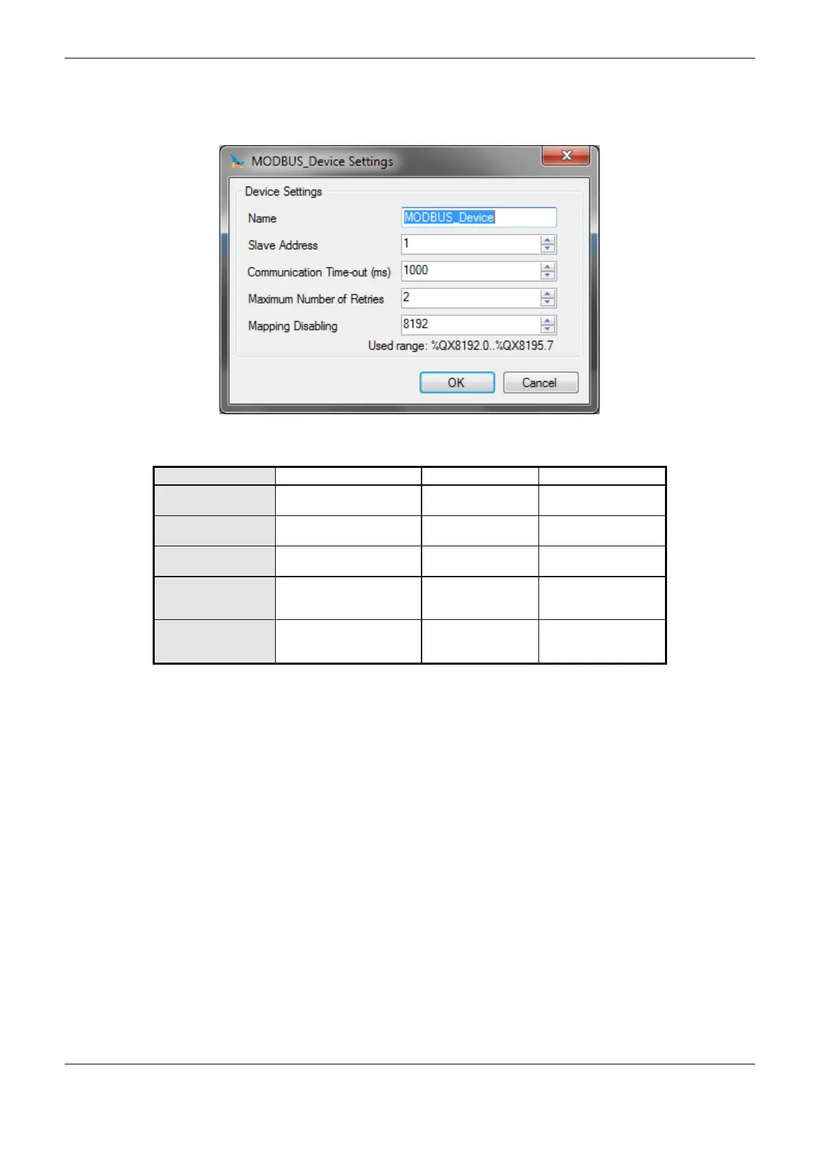
The configuration of the slave devices, viewed in Figure 4-19, comprises the following parameters:
Figure 4-19. Device Configuration
Identifier, according to
IEC 61131-3
Communication
Time-out (ms)
Sets the time-out of the
application level
Maximum Number
of Retries
Sets the number of retries
before reporting a
communication error
Initial address used to
disable MODBUS
relations
Table 4-54. Device Configuration - MODBUS Master
Notes:
Instance Name: this field is the identifier of the device, which is checked according to IEC 61131-3,
i.e. does not allow spaces, special characters and start with numeral character. It’s limited in 24
characters.
Mapping Disabling: composed of 32 bits, used to disable, individually, the 32 MODBUS relations
configured in Device Mapping space. The relation is disabled when the bit, corresponding to relation,
is equal to 1, otherwise, the mapping is enabled. This field is limited by the size of outputs variables
(%Q) addressable memory of each CPU, which can be found in chapter Technical Description.
Default Value: the factory default value cannot be set to the Disabling Area of Mappings field,
because the creation of a Protocol instance may be held at any time on application development. The
MasterTool IEC XE software itself allocate a value, from the range of output variables of direct
representation (%Q), not used yet.
For further details on the slave address, time-out and maximum number of retries parameters see
notes in section Devices Configuration – Configuration for Direct Representation (%Q).
 Loading...