4. Configuration
89
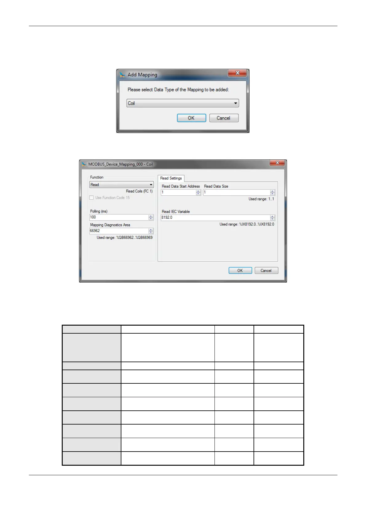
Mappings Configuration – Configuration for Direct Representation (%Q)
The MODBUS relations settings, viewed in Figure 4-20 and Figure 4-21, follow the parameters
described in Table 4-55:
Figure 4-20. MODBUS Data Type
Figure 4-21. MODBUS Function
In Table 4-55, the number of factory default settings, and the values for the column options, may
vary according to the data type and MODBUS function (FC).
Read
Write
Read/Write
Write Mask
Communication period (ms)
Initial address of the MODBUS relation
diagnostics (%Q)
Initial address of the MODBUS read
data
Number of MODBUS read data
Depends on the
function used
Initial address of the read variables
(%I)
Initial address of the MODBUS write
data
Number of MODBUS write data
Depends on the
function used
Initial address of the write variables
(%Q)
 Loading...