MM-400A
8. Operation Screens
8-72
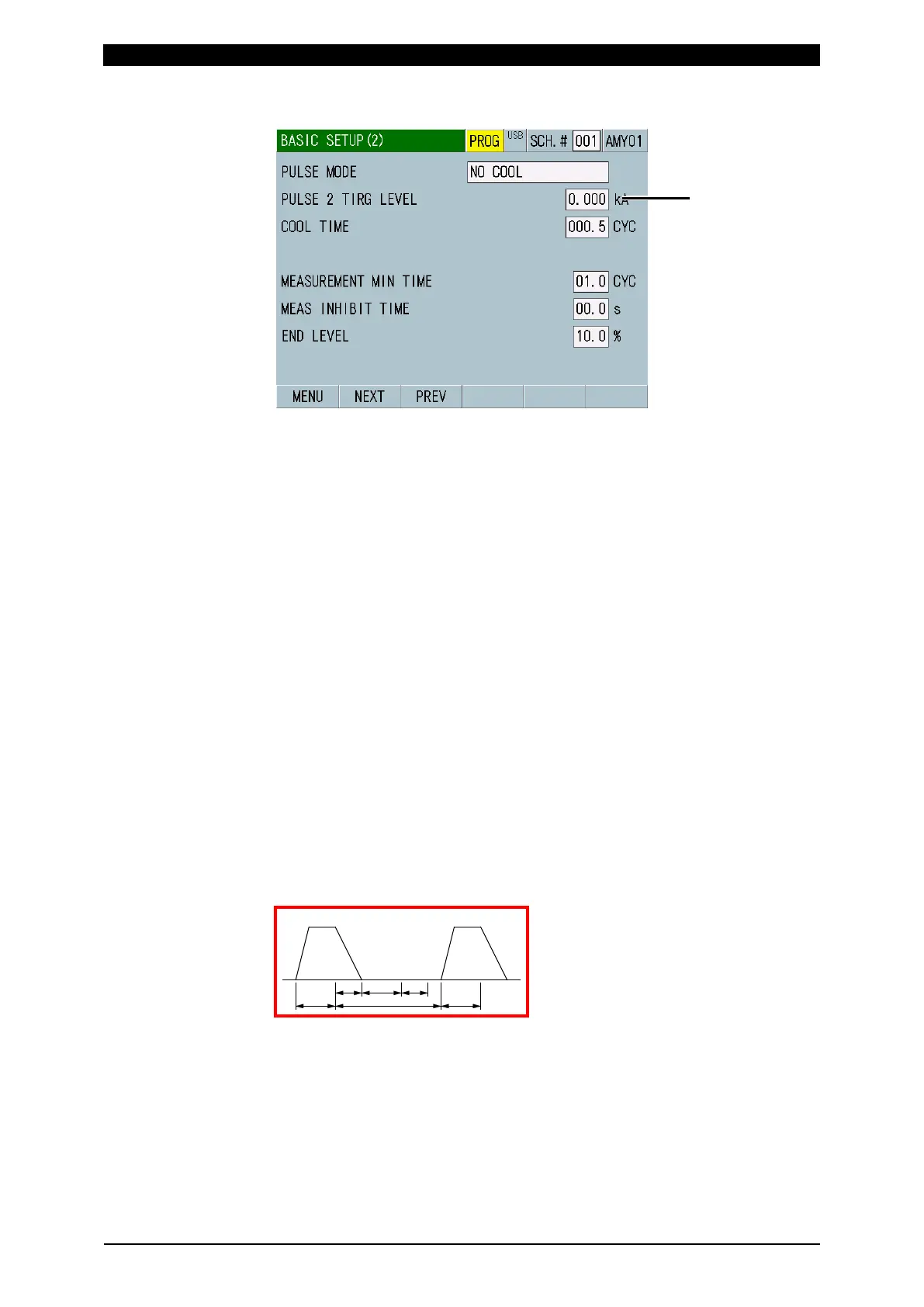
When PULSE MODE is NO COOL
(1) SCH.#
Shows the measurement schedule number used (1 to 127). On the other hand,
you can change schedules by selecting this field and inputting a value.
(2) Schedule name
Shows the name of SCH.#. This can be set in the BASIC SETUP (1) screen.
(3) PULSE MODE
For a standard single pulse spot welding, select SET PULSE for PULSE
MODE, and “00” for PULSE No.
Current may be passed several times in a single welding sequence. Use the
impulse settings to measure an arbitrary step, all steps, and the second step in
the 2-step welding with no cooling time. Waveforms of all numbers of
measured times are displayed.
(Note) Current flow interval
The cooling time of the welding power supply should be longer than the
following current flow interval (time that current does not flow). If the time is
shorter, the impulse measurement cannot be performed. The current flow
interval should be longer than c + d + e shown below.
For COOL TIME of MM-400A, set the time shorter than that of the welding
power supply. (Use the initial setting of 0.5 CYC or 1 ms.)
Also, when COOL TIME of MM-400A is longer than that of the welding power
supply, the measurement is performed as the same pulse.
a: WELD (weld time of the welding power supply)
b: COOL (downtime of the welding power supply)
c: Time until current falls below the END LEVEL setting
d: Time set in COOL TIME
e: 1 CYC when TIME is CYC, 2 ms when TIME is ms
For TIME, refer to Chapter 8, “l-1. BASIC SETUP (1) Screen.”
Even if the impulse settings are used, a welding longer than the following
measurable time cannot be measured. The cooling time is included.