MM-400A
9. Measurement
9-15
Item Setting
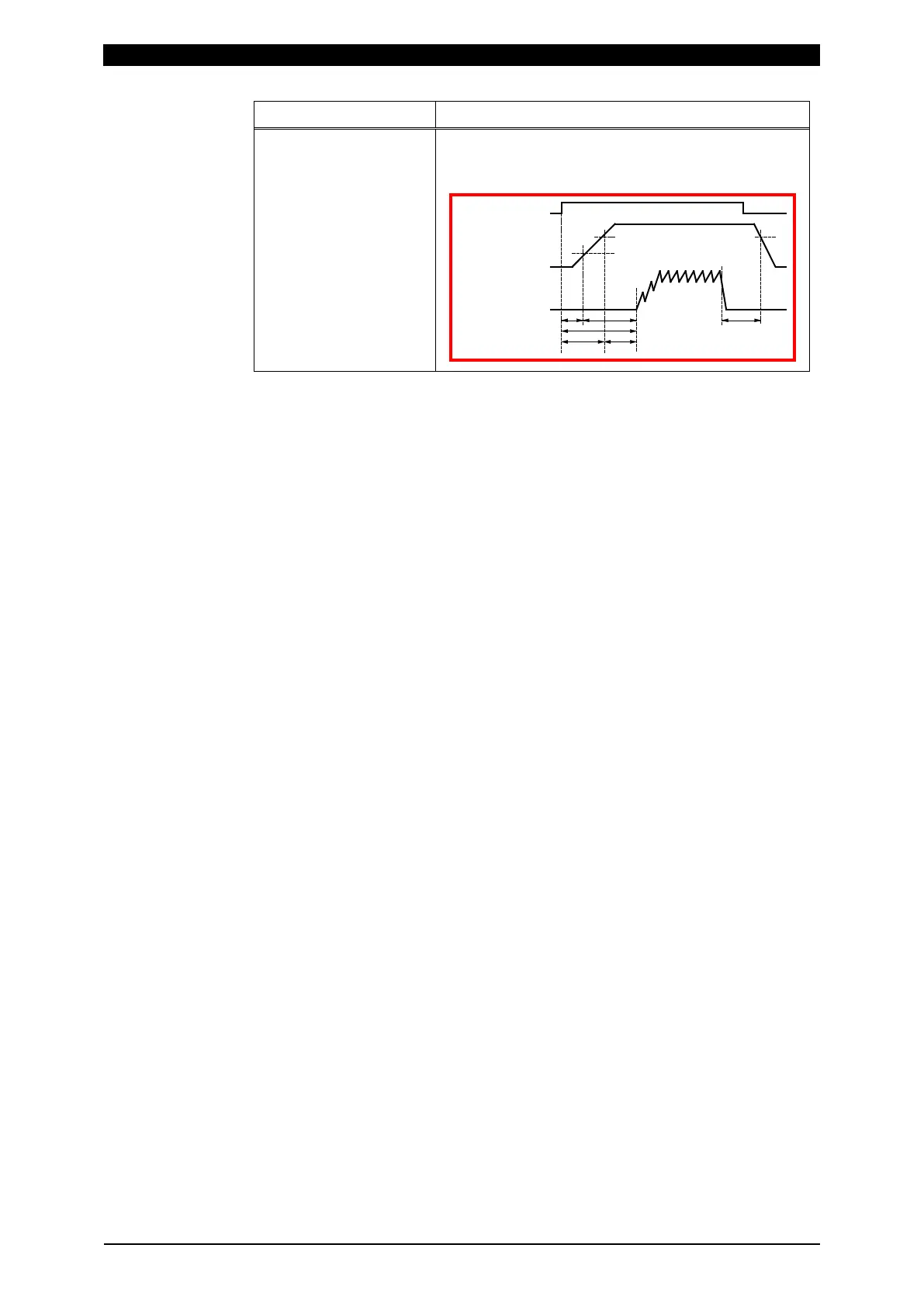
RISE LEVEL
FALL LEVEL
Set RISE LEVEL and FALL LEVEL as the ratio to
the peak (10 to 90%). This setting applies to the
time measurements in the FORCE TIMING screen.
Force
C
u
rrent
FALL LEVELRISE LEVEL
TRIGGER LEVEL
"FORCE TRIGGER"
External input signal
(1)
(3)
(2)
(5) (6)
(4)
10) According to the desired measurement item, set the following in one of
MEASUREMENT 1 to 5: (For information on measurement items other than the
following, refer to (2) c in Chapter 8.)
To measure mean force of measurement interval 1: FORCE AVG1
To measure mean force of measurement interval 2: FORCE AVG2
To measure peak force: FORCE PEAK
To measure force before the start of current flow: FORCE INITIAL
To measure force after the end of welding: FORCE FINAL
To measure force constantly by the constant trigger: FORCE REAL TIME
To measure the force time (from when the force signal exceeds the force start
level to when the signal falls below the force end level): FORCE TIME
When the measurement item is changed, upper and lower limits for the
changed measurement item are initialized. Set upper and lower limits again on
the COMPARATOR screen. (Refer to (2) e in Chapter 8.)
11) To display the waveforms of force, set those items in WAVEFORM 1 to 4.
12) Touch the MENU key to select MEASUREMENT or WAVEFORM.
13) Select a schedule number to measure.
When setting by the touch panel, set a schedule number to measure in
“SCH.#” without inputting a signal to the external input (SCH1 to 64).
When selecting by the external input (SCH1 to 64), input a signal in the
external input (SCH1 to 64). (Refer to (1) (2) in Chapter 10.)
14) Touch PROG to change it to MEAS, putting the MM-400A into wait state until
measurement starts (the signal selected as trigger is input).
15) When the trigger signal is input to the MM-400A, the [TRIGGER] lamp lights
up and measurement starts. Confirm the measurement results on the
MEASUREMENT and WAVEFORM screens. You can also print measured
values and waveforms from the PRINT screen, as necessary.