MM-400A
6. Installation and Connections
6-4
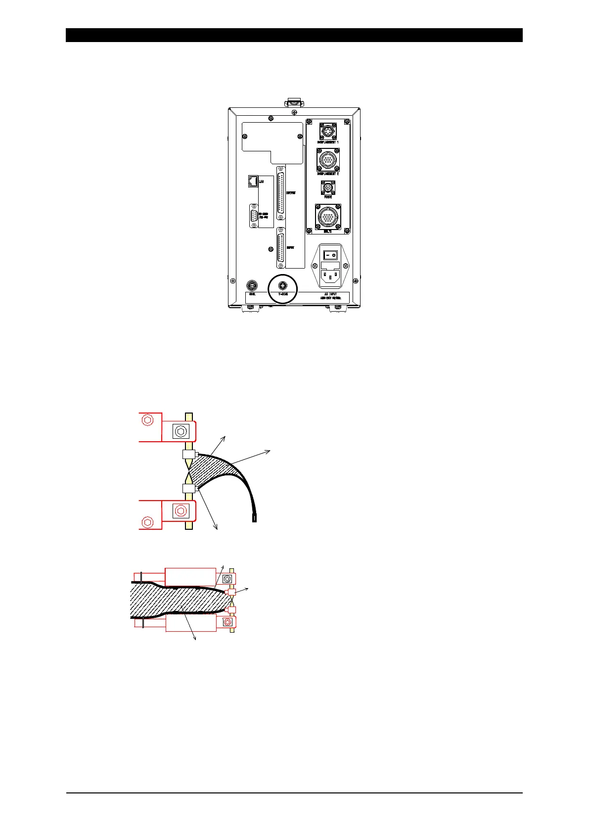
3) Plug the voltage detection cable connector into the voltage detection cable
connector [V-SENS] on the rear panel of the MM-400A.
4) Connect the voltage measurement cables to the electrodes (positive/negative).
(Note) To properly perform a voltage detection
The voltage detection cable picks up voltage induced by the welding current. To
measure the voltage between the tips, connect the cable as shown below.
Make the distance between clips as small as
possible, and twist the lead wires together so
that induction voltage is reduced and the
voltage between tips can be measured
accurately.
When the voltage detection cable wires are
placed as shown to the left, voltage induced
by the welding current is added to the voltage
between tips. When monitoring voltage,
fasten the lead wires so that the loop space S
does not change and induction voltage does
not fluctuate.
Voltage detection lead wire
Clip
Loop space S