MM-400A
12. Data Communication
12-23
Timing for the bi-directional
data communication
Restrictions
Not during measurement None
During the bi-directional data
communication
After completing the response of the previous data
communication, perform the next data communication.
(Note 4) In response to a write request, writing in the flash memory starts. The flash
memory has the rewriting limit (about 100,000 times). Be careful when writing frequency.
(Note 5) When SEAM is selected for MODE in the SYSTEM SETTING (1) screen, data
of 1) MEASUREMENT to 6) HISTORY OUT OF LIM of (3) Communication Protocol
(Single-Directional Communication) cannot be read.
(Note 6) When reading data of 1) MEASUREMENT to 4) FORCE ALL CYCLE of (3)
Communication Protocol (Single-Directional Communication), only data displayed on the
MEASUREMENT, WAVEFORM or ALL CYCLE screen is output. When reading past
measured values on the HISTORY screen, the read out data is output. Also, when
measuring the multi-step welding with SET PULSE, data of the specified step is taken
out. When measuring the multi-step welding with ALL PULSE settings, data of the 1-step
welding is taken out. To output all measured data, use the single-directional
communication.
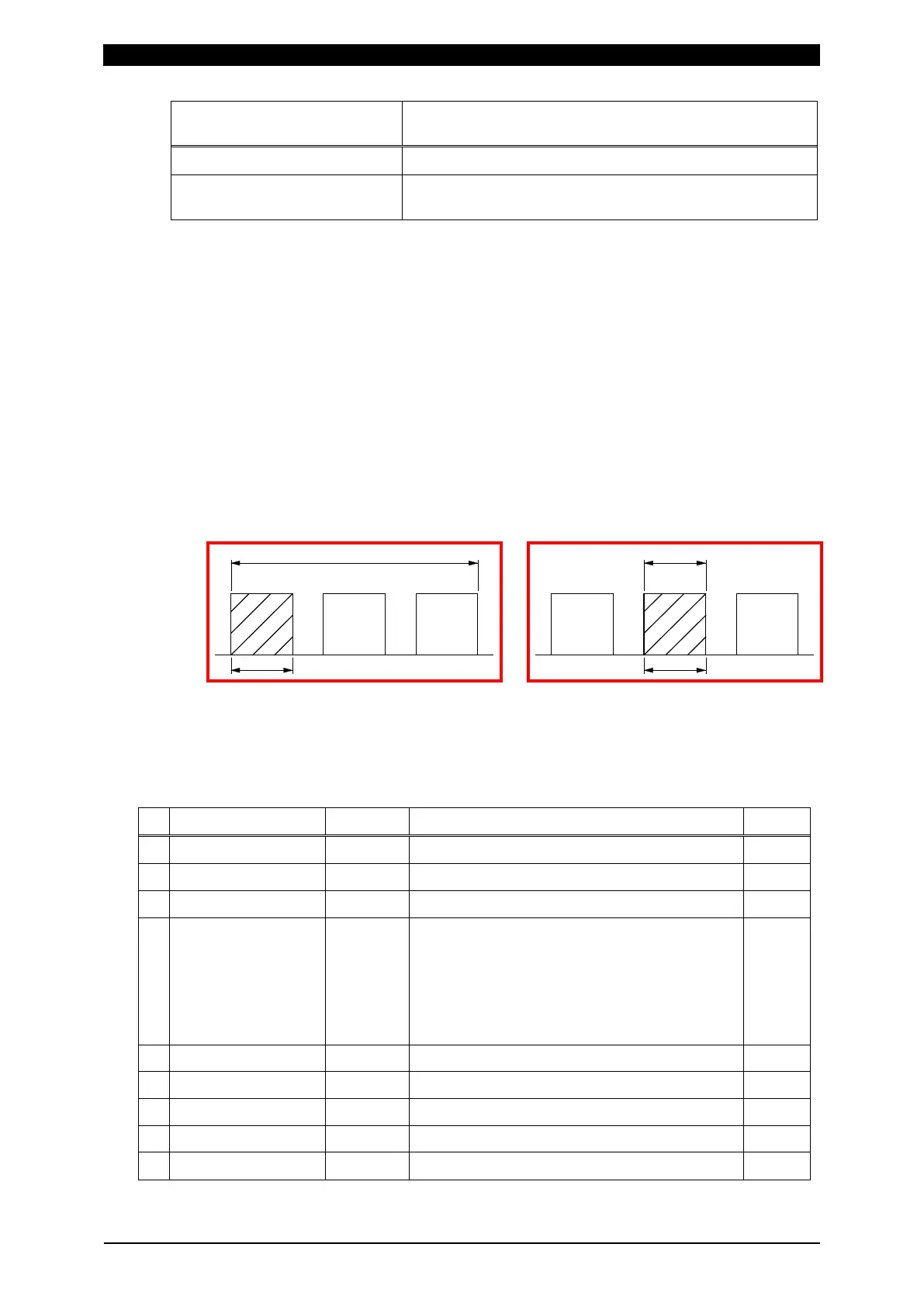
Ex.) When measuring the 3-step welding in the impulse setting
ALL PULSE settings SET PULSE with PULSE No. “2”
a: Data of 1) MEASUREMENT, 3) CURR ALL CYCLE and 4) FORCE ALL CYCLE
b: Data of 2) WAVEFORM
• Reading request data
Item Display Range Length
1 Start code # 1
2 ID NO. 01 01 to 31 2
3 Read code R R: read 1
4 SCH.# 001 000: (measurement data in the last
MEASUREMENT, WAVEFORM, CURR ALL
CYCLE, FORCE ALL CYCLE, HISTORY, and
HISTORY OUT OF LIM. Setting data of
common to all schedules)
001 to 127: (schedule data of each schedule)
3
5 Screen code S 1
6 Item No. 01 01 to 24 (Refer to the Item number data table.) 2
7 All contents * 1
8 Return code [CR] (0x0d) 1
9 Feed code [LF] (0x0a) 1
b
a
Pulse 1 Pulse 2 Pulse 3