3.2 Basic Operation
3-21
3
Measurement
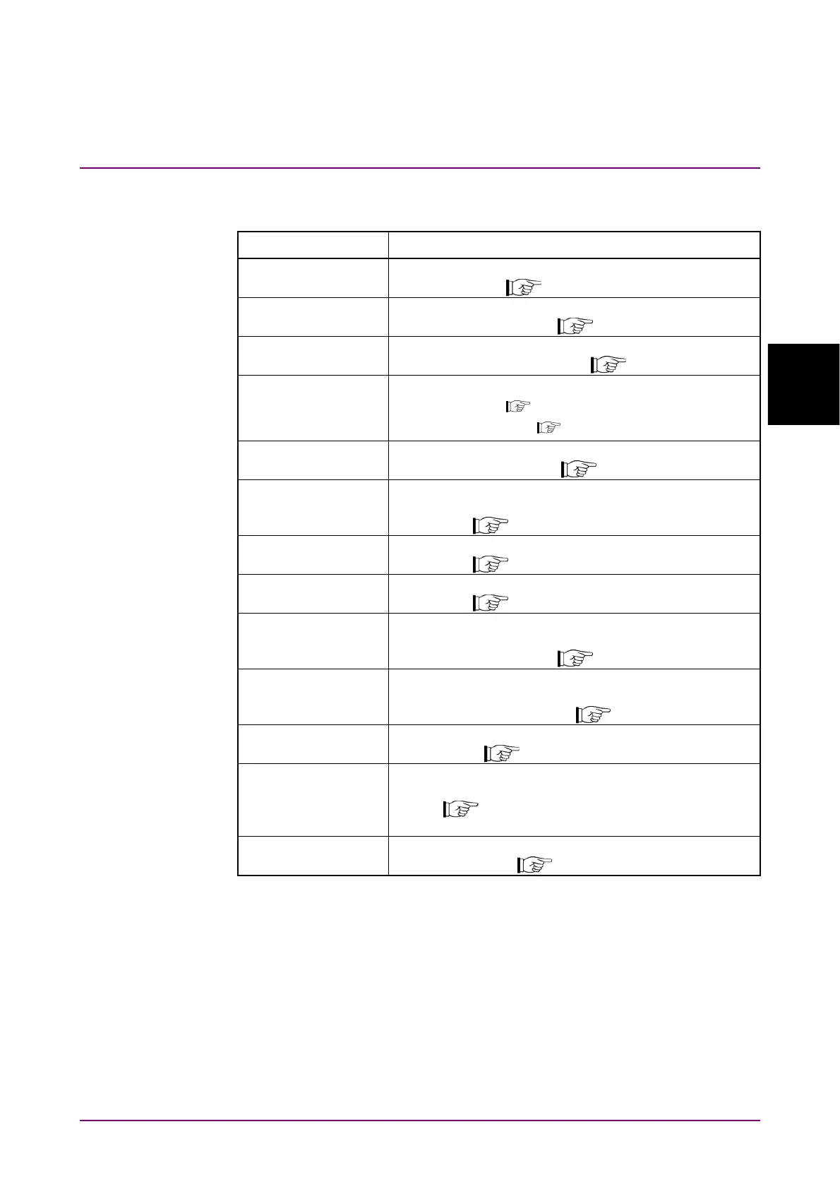
Table 3.2.2.5-1 Description of RX Mode Main Function Menu
(Audio Analyzer +RF Signal Generator Screen)
Menu Display Function
Mode
Sets the measurement mode.
3.3 “Setting Measurement Mode”
Frequency
Sets the frequency.
3.7.1 “Setting frequency”
Amplitude
Sets the level.
3.7.2 “Setting level”
Measure
Sets measurement items.
3.7.3 “Setting measurement items”
3.9 “Audio Analyzer Function”
AF Setting
Sets AF signal.
3.7.4 “Setting AF signal”
Signal Output
Restart
Restarts transmission output of modulation wave
signal.
3.8.1 “Setting modulation wave signal”
Signal Modulation
Sets modulation for output signal.
3.8.1 “Setting modulation wave signal”
Signal Output
Sets signal output On/Off.
3.8.1 “Setting modulation wave signal”
Average
Sets whether to set averaging.
Setting items are the same as TX mode.
3.4.6 “Setting averaging”
Marker
Sets marker.
Setting items are the same as TX mode.
3.4.7 “Setting marker”
Monitor Volume
Sets demodulation monitor volume.
3.4.5 “Setting demodulation monitor”
Audio Func. Setting
Sets input/output of the terminal to control external
device.
3.10 “Setting Terminals for External Device
Control”
Accessory
Performs settings for other functions.
5.1 “Selecting Other Functions”