Service Manual i2000SR interface module
625798100.APS.5.doc Page 13 of 212
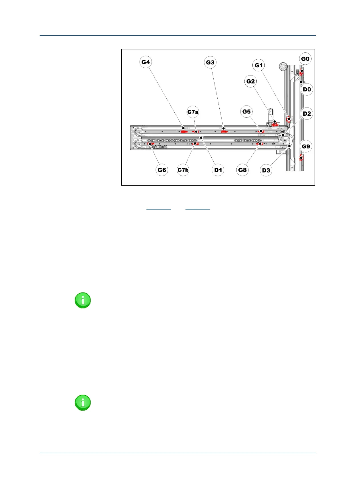
Figure 4 – Stop gates (G#) and diverters (D#)
Brief description of the stop gate devices
Refer to
Figure 4
and
Figure 9
.
Gate 0 – (G0) is located on the APS Track and is operated by
electro valve EV1. This Type 3 gate operates when the carrier
moving along the APS main track is either diverted into the
i2000SR IM or continues along the APS track. If the carrier is
diverted, Gate 0 and the standard track diverter (D0) activate to
route the carrier to the IM. The diverter (D0) is operated by
electro valve EV2.
Gate 0 is also used to maintain the number of carriers in the
queue of the i2000SR IM instrument interface.
NOTE:
The number of carriers queued at the Instrument Gate (G0)
is set by the value in the Instrument Gate parameter of the
Config Wizard Track Layout. The value of the standard
instrument interface queue is ten (10).
Gate 1 – (G1) is the Entry gate and is located on the Pit Stop lane
of the APS track and is operated by electro valve EV3. This Type 1
gate operates when the i2000SR IM is used with the APS. The
gate is normally closed and will only open to allow carriers from
the track to enter Lane 1 when there is no possibility that it would
interfere with an Off-line carrier from the IM lane 3.
NOTE:
The number of carriers queued at the Entry Gate (G1) is set
by the value in the Return/Entry Gate parameter of the
Config Wizard Track Layout screen. Typically the value is
set to eight (8) as that is the number of carriers that can
physically be placed in the area. (Refer to figure 1)