Service Manual i2000SR interface module
625798100.APS.5.doc Page 23 of 212
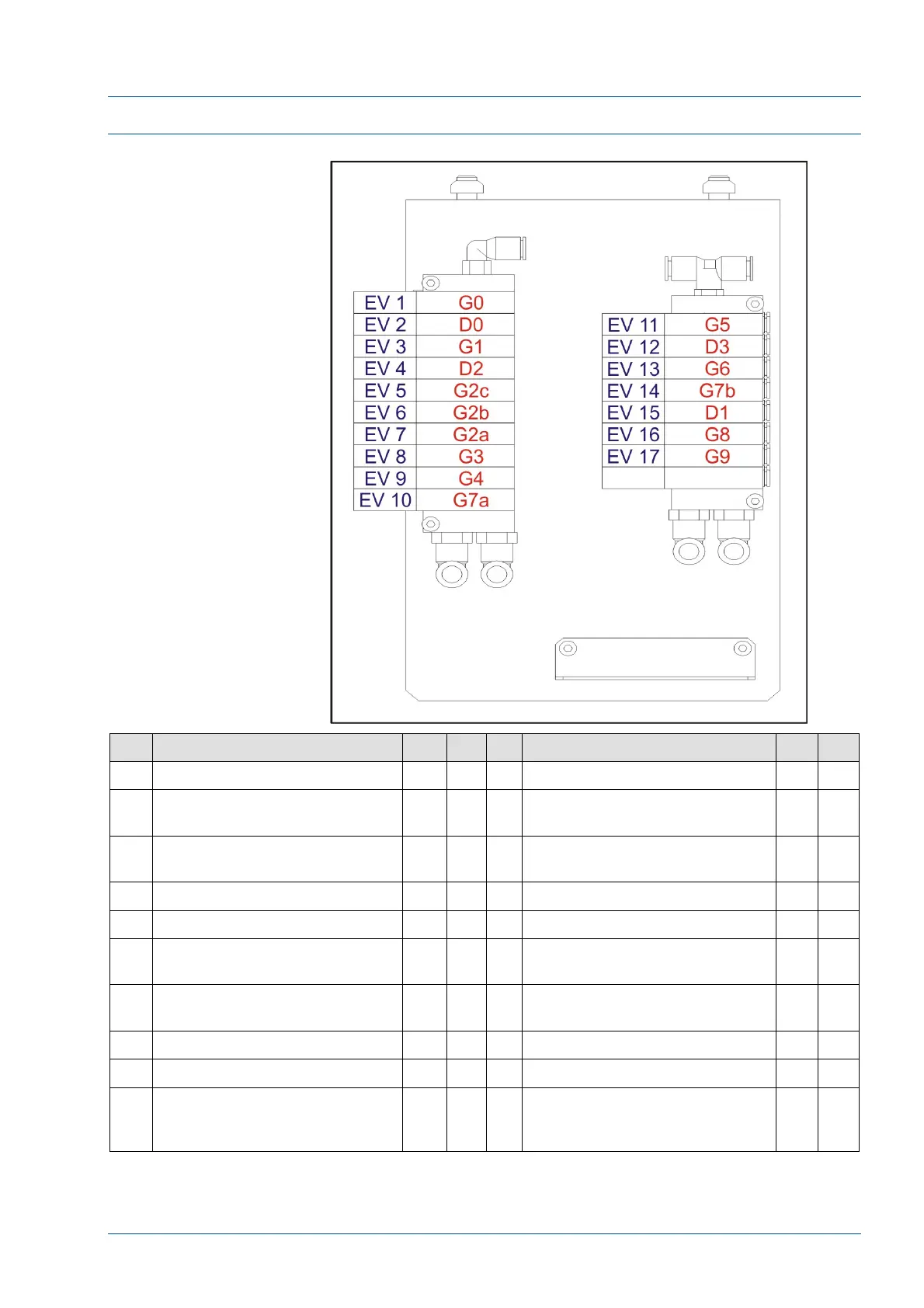
i2000SR IM Pneumatics Components
Figure 8 – i2000SR IM pneumatic panel
EV Description Gate
Port
EV Description GatePort
1 Instrument i2000SR Gate G0 A 11 Exit Gate G5 A
2
Instrument i2000SR Divert
Gate
D0 AB 12
Divert to Track
D3 AB
3 Entry Gate G1 A 13
Output Gate – release off-line
carriers to lane 3
G6 A
4 Divert Gates at end of lane 3 D2 AB 14 Routine Entry G7b
A
5 BCR Stop Gate G2a B 15 Routine Entry diverter – L3 to L2
D1 AB
6 BCR Carrier Rotation G2b B 16
Priority off-line carrier entry
gate
G8 A
7 BCR 2nd carrier Stop Gate G2c A 17
Stop Gate to prevent carrier
collision on APS Track
G9 B
8 i2000SR STAT Pipetting Gate G3 A
9 i2000SR Sample Pipetting Gate
G4 A
10
Routine Entry Anti-collision
gate – lets in the off-line
routine samples to L2
G7a B