i2000SR interface module Service Manual
Page 86 of 212 625798100.APS.5.doc
IOM Pneumatic Panel Differences
Below are schematics of the original (P/N 510.500.001) and new
(P/N 510.500.002) Pneumatic Panels
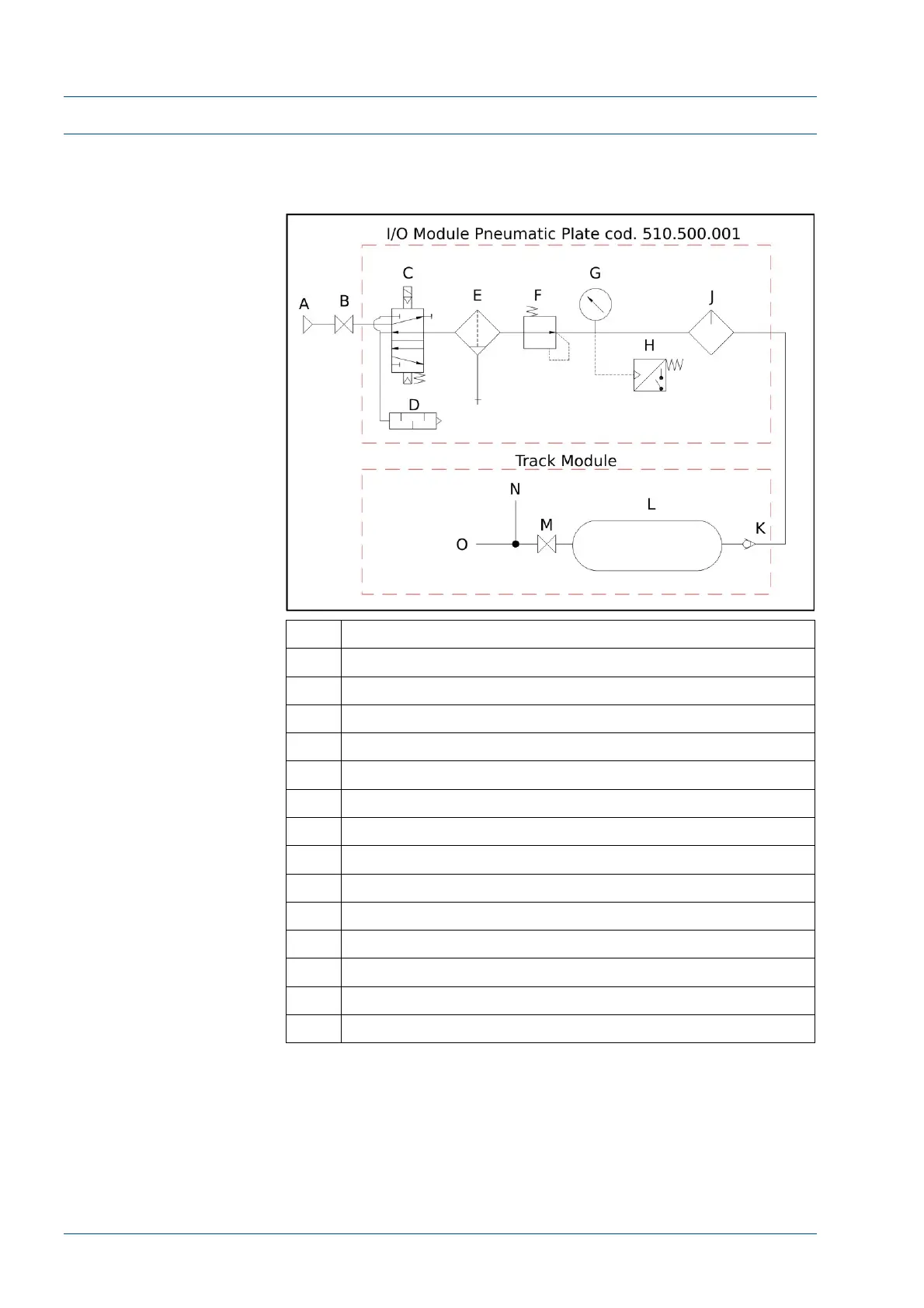
Figure 71 – Pneumatic Panel (Original) P/N 510.500.001
No. Description
A Compressed air IN (from 0.7 to 0.9 MPa >150 Nl/min)
B ON/OFF Valve
C Solenoid Valve for IOM and Workcell
D Silencer
E Micro Filter
F Pressure regulator
G Pressure indicator
H Minimum Pressure Switch (0.52 MPa)
J Micro filter
K No return valve
L Tank
M ON/OFF valve
N To the I/O Module Robot
O To the Track Module
To provide the i2000SR IM with an air source that is independent
of the IOM air valve, a manifold has been added. After the site air
is filtered [E], regulated [F] and stored in the TMA tank [L], the
air is routed to a manifold [R] with manual distribution valves [P &
Q] and port to the IOM air valve [C].