Service Manual i2000SR interface module
625798100.APS.5.doc Page 53 of 212
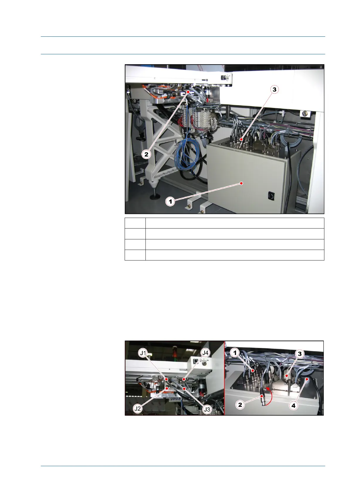
Electrical Connections
Figure 30 – Electrical components
No. Description
1 Electrical box
2 IM Connector panel
3 Antennae, power, and control connectors
• If the installation of the i2000SR is a retrofit, install the
electrical box on the TMA in a location that the TAG Reader LEDs
can be observed as carriers are placed on an antenna.
• If the installation of the i2000SR is a new installation, the
electrical box is already installed on the TMA.
• electrical connections.
Figure 31 – Electrical connections