Service Manual i2000SR interface module
625798100.APS.5.doc Page 29 of 212
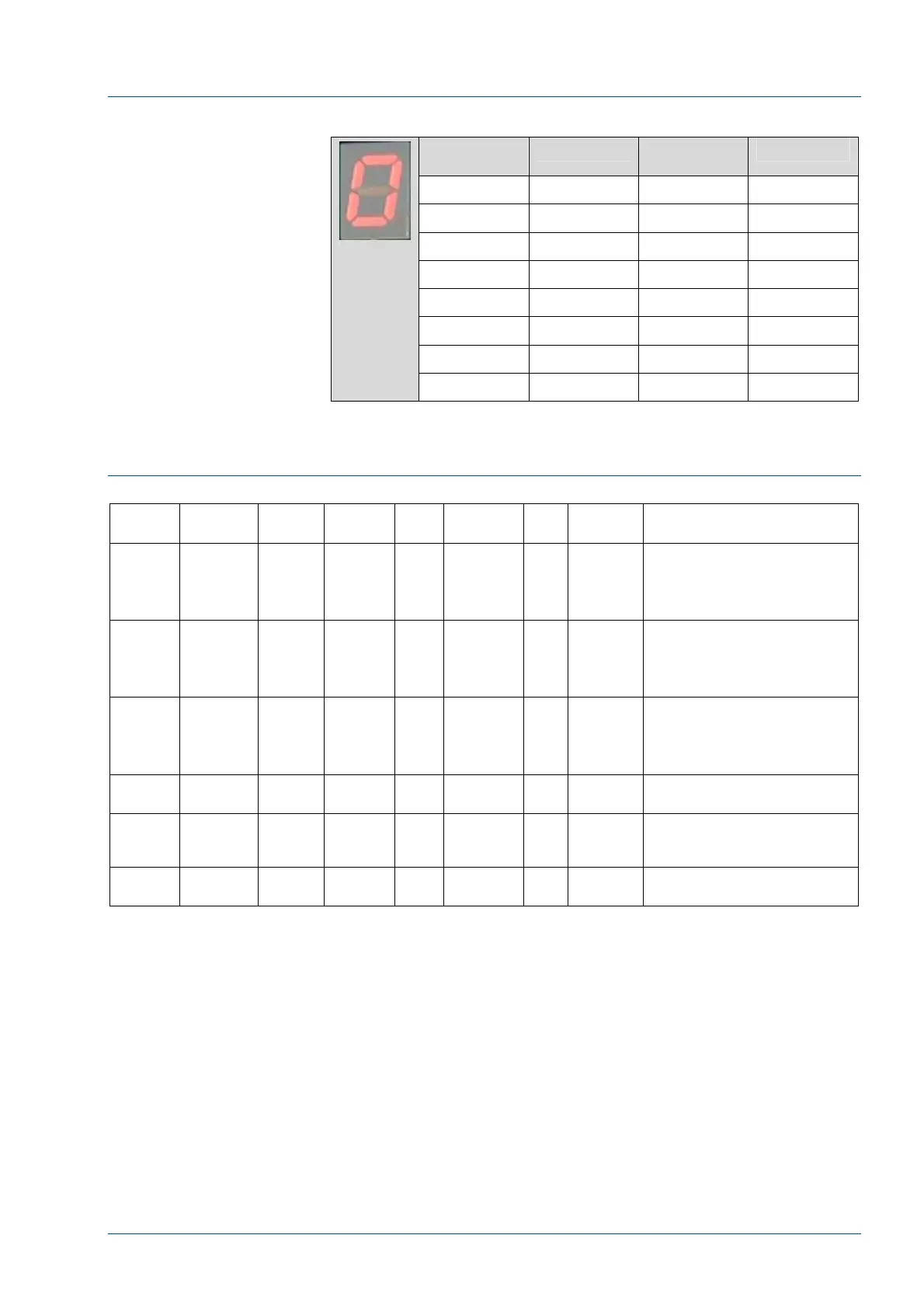
SLAVE 0 CAN Board Segment Indicator
LED
Indicator
Carrier at G0 Carrier at
G2a
Carrier at G1
0
1 Yes
2 Yes
3 Yes Yes
4 Yes
5 Yes Yes
6 Yes Yes
7 Yes Yes Yes
SLAVE 1 CAN Board Description
Table 4 – Slave 1 CAN Board Inputs
Pin Function Device Electro
Valve
Port Antenna LED Control
Devices
Description
In – 1 Tube
Presence
G6 Diag –
Bit 16
1 = ON
0 = OFF
Tube detected at the output
(left end of Lane 4)
In – 2 Tube
Presence
G7 Diag –
Bit 17
1 = ON
0 = OFF
Tube detected at Routine Input
In – 3 Tube
Presence
G8 Diag –
Bit 18
1 = ON
0 = OFF
Tube detected at Priority Input
In – 4 to
7
Not Used Not Used
Exp.
Out – 1
to 8
Not Used Not Used
Exp. In –
1 to 7
Not Used Not Used