Service Manual i2000SR interface module
625798100.APS.5.doc Page 43 of 212
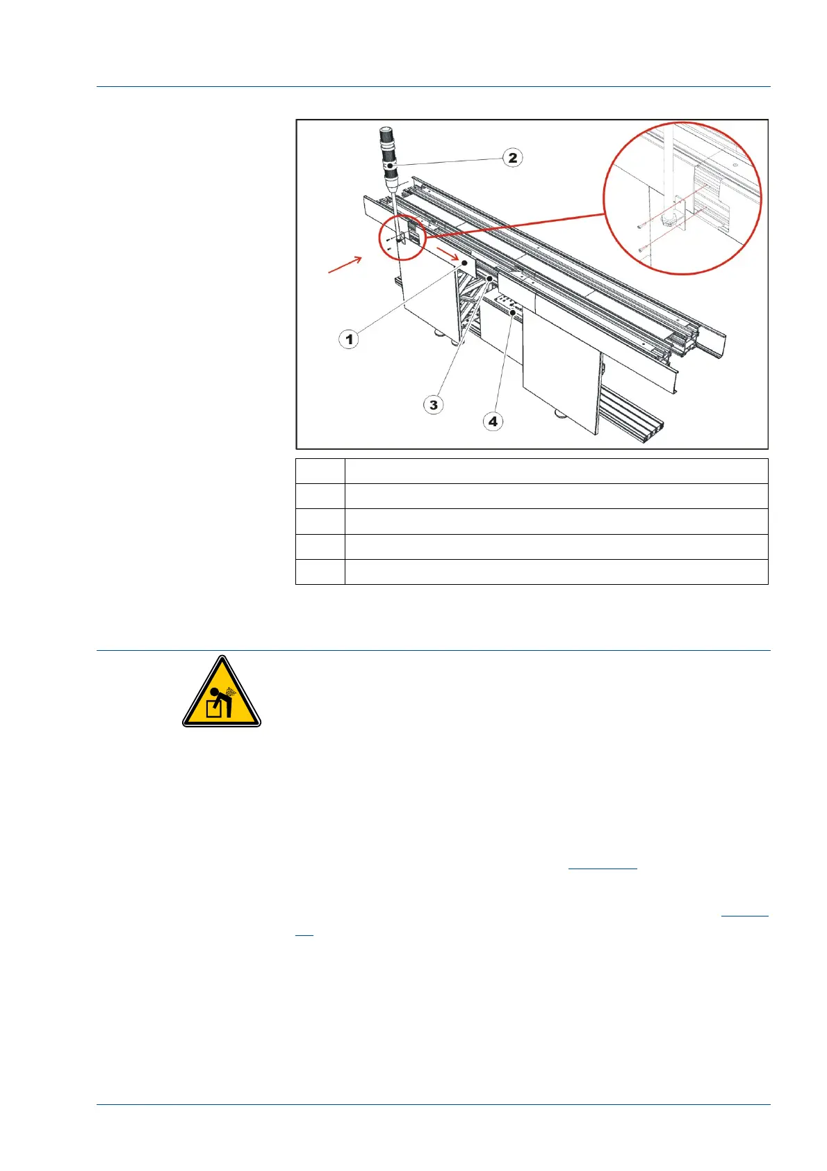
Figure 16 – Pole mounting
No. Description
1 Side top cover to shift
2 Instrument Indicator Light (Light pole assembly)
3 i2000SR IM installation point
4 Electrical box
Installation of the i2000SR IM
CAUTION: Lifting Hazard
The installation of the i2000SR IM to the TMA module
requires two service personnel: one person to hold the
i2000SR IM module and the other to fasten bolts. The
i2000SR IM gross weight is 18 kg (40 lbs).
• Before starting the assembly on the i2000SR IM, verify the
position of the cable exiting from the optical sensor on the main
track. It must be oriented as shown in
Figure 17
.
• Using the screws provided, mount the Disk upper
protection [1] and fasten it to the TMA upper profile (See
Figure
18
).
• The Disk upper protection [1] has two slots that allow its
position to be adjusted horizontally.
• Remove the i2000SR IM group from the shipping pallet
and remove from the packaging material.
• Before installing the IM, locate the pneumatic multi
connectors base and remove it by unscrewing its two (2) M4 fixing