i2000SR interface module Service Manual
Page 44 of 212 625798100.APS.5.doc
screws. (See
Figure 20
). This action allows the IM mounting
screws to be accessed more easily.
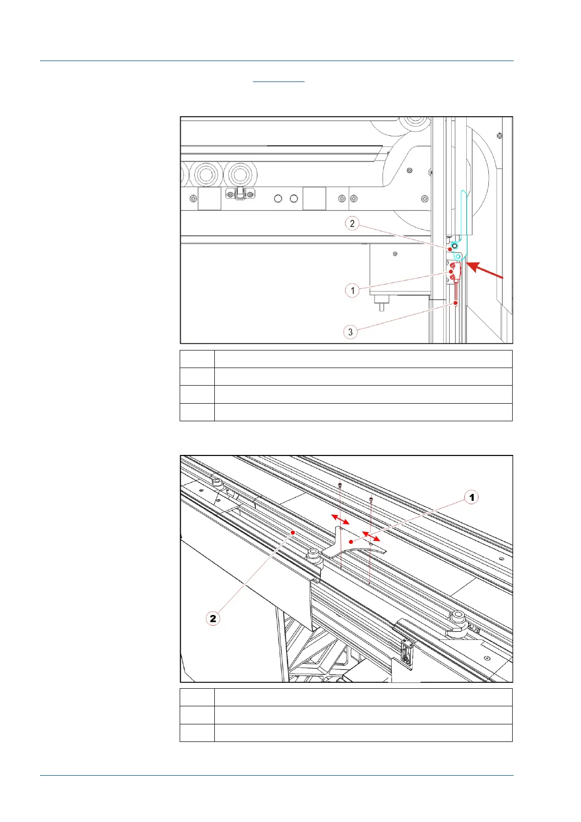
Figure 17 – Right orientation of the optical sensor cable
No. Description
1 Optical sensor body (on the main track)
2 Diverter lever (after i2000SR IM installation)
3 Optical sensor cable
Figure 18 – Disk protection
No. Description
1 Disk upper protection
2 TMA profile