Service Manual i2000SR interface module
625798100.APS.5.doc Page 49 of 212
Pneumatic Connections
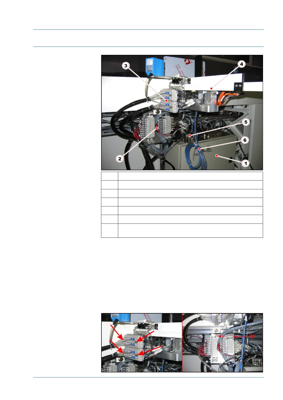
Figure 25 – Pneumatic panel and electrical panel
No. Description
1 Electrical box
2 Pneumatic panel
3 Pneumatic multi connectors
4 i2000SR IM track
5 Antennas connectors on electrical box
6 Cables for future CAN-BUS development that are not
currently used
• If the installation of the i2000SR IM is a new workcell
installation, the pneumatic panel is already installed and the only
operation required is to assemble the two pneumatic multi
connectors.
• If the installation is an upgrade, mount the pneumatic
panel in a position in front of the i2000SR IM. In this manner,
when the valve solenoid is manually pressed, the valve action can
be observed.
Figure 26 – Multi connectors and pneumatic panel