Service Manual i2000SR interface module
625798100.APS.5.doc Page 19 of 212
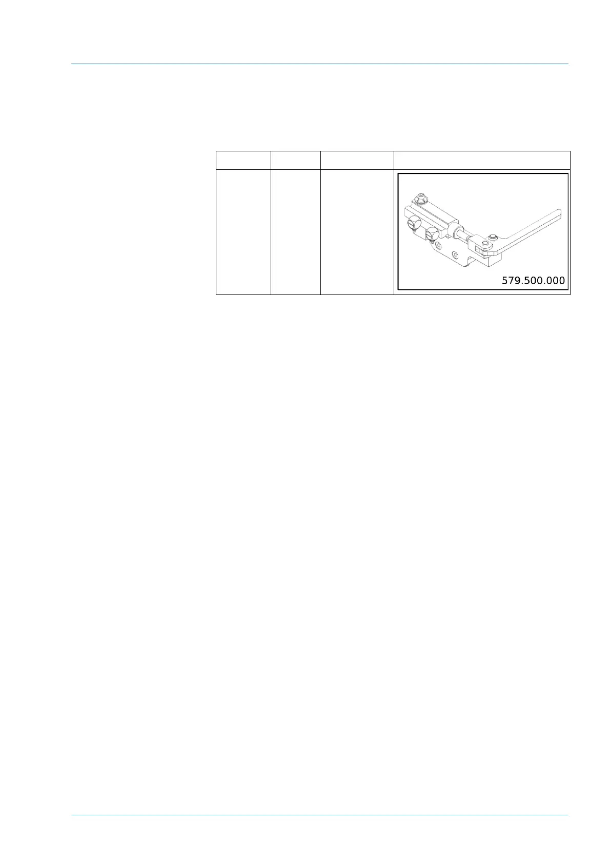
D3 – Lane 4/Track Diverter – is in the area of the large disk. It is
controlled by EV12 and is activated to block carriers traveling on
the large disk from entering Lane 4. Carriers are then routed to
the Main Track. The diverter is normally retracted and allows
carriers to travel around the large disk.
Diverter
Control
Description
Reference
D3 EV12
Lane
4/Track
Diverter
IM Antenna and Optical Sensors
The i2000SR IM uses RFID Antenna and optical sensors to detect
the presence of a carrier and/or sample tube. These devices are
controlled by the F/W in the Master/Slave board located in the IM
electrical box.
An antenna is located at each of the nine gates and is used to
detect the RFID of the carrier located at the associated gate
location.
There are three tube sensors that are used to detect the presence
of a tube in a carrier. When a tube is placed into the first carrier
of a routine (G7b) or priority (G8) input location, it is detected by
the associated tube sensor. As the tube is routed to the Exit Gate
(G6), the tube sensor at that location is used to ensure that the
carrier does not contain a tube before it is routed to a tube input
queue.
The routine (G7b) and priority (G8) inputs have green and yellow
LEDs used to notify the user of the status of the carrier located at
the gate. A green LED illuminates to indicate the carrier is ready
for a tube to be inserted. A blinking yellow LED indicates that the
carrier is scheduled to move and a steady yellow LED illuminates
to indicate a moving carrier.
If the carrier on the disk is an On-line carrier, an optical sensor is
located on the main track near D3 to detect that the large disk to
the main track properly routs the carrier. The sensor is also used
to activate the main track gate (G9) to prevent a collision.
A second carrier sensor is located at the large disk near D2b to
detect that the Off-line carrier is properly routed to lane 4.