i2000SR interface module Service Manual
Page 28 of 212 625798100.APS.5.doc
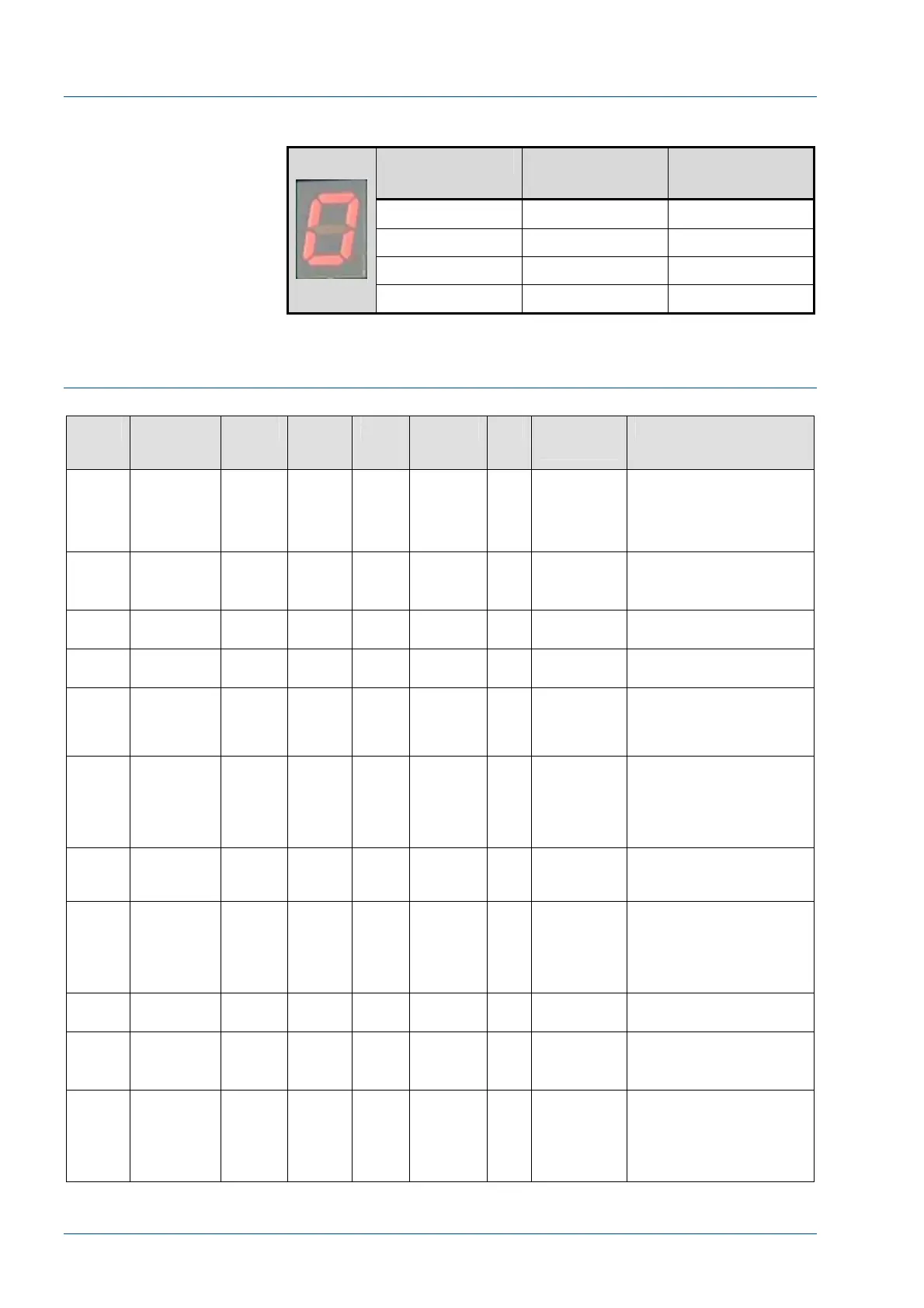
MASTER CAN Board Segment Indicator
LED Indicator Carrier at G3
STAT Probe
Carrier at G4
Sample Probe
0
1 Yes
2 Yes
3 Yes Yes
SLAVE 0 CAN Board Description
Table 3 – Slave 0 CAN Board Inputs - Outputs
Pin Function Device Electr
o
Valve
Port Antenna LED Control
Command
Description
Out – 1 Instrument
Gate
G0 EV1 A A0 1 Divert Gate
- Pass
(Pass A)
Activated to either pass a
carrier along the main
track or in conjunction with
diverter D0 route it to IM
entry
Out – 2 Pit stop D0 EV2 A & B Divert Gate
- Pit Stop
(Pit Stop)
Activated to divert a
carrier into the IM entry
Out – 3 Gate at
BCR
G2a EV5 B A2 2 BCR Pass Activated to pass a carrier
at the BCR reader.
Out – 4 Lock Gate
at BCR
G2b EV6 B BCR Lock Activated to lock carrier at
BCR to cause it to spin.
Out – 5 Gate before
BCR
G2c EV7 A Activated to prevent next
carrier from impacting the
spinning of a carrier at the
BCR.
Out – 6 Routine
Tube
Insertion
Green LED
Diag – Bit
13 (Routine
Green LED)
1 = ON
0 = OFF
Activated to indicate that
the condition is correct to
insert tube at routine
location
Out – 7 Entry gate G1 EV3 A A1 4 Pass
Entry Pass
Activated to release
carriers from the IM entry
to Lane 1
Out – 8 Routine
Tube
Insertion
Yellow LED
Diag – Bit
15 (Routine
Yellow LED)
1 = ON
0 = OFF
Activated to indicate that
the conditions are not
correct to insert tube at
routine location
In – 1
to 7
Not Used Not Used
Expans
ion
Out –1
LUI – Pause
button LED
Keypad
Keypad – Pause LED
illuminated
Expans
ion Out
– 2
Post Lamp
– Yellow
K4 Diag – Bit 3
(Yellow
Lamp)
1 = ON
0 = OFF
Activates relay K4 to turn
on the Yellow lamp
(indicate non operational
status that requires
operator attention)