i2000SR interface module Service Manual
Page 32 of 212 625798100.APS.5.doc
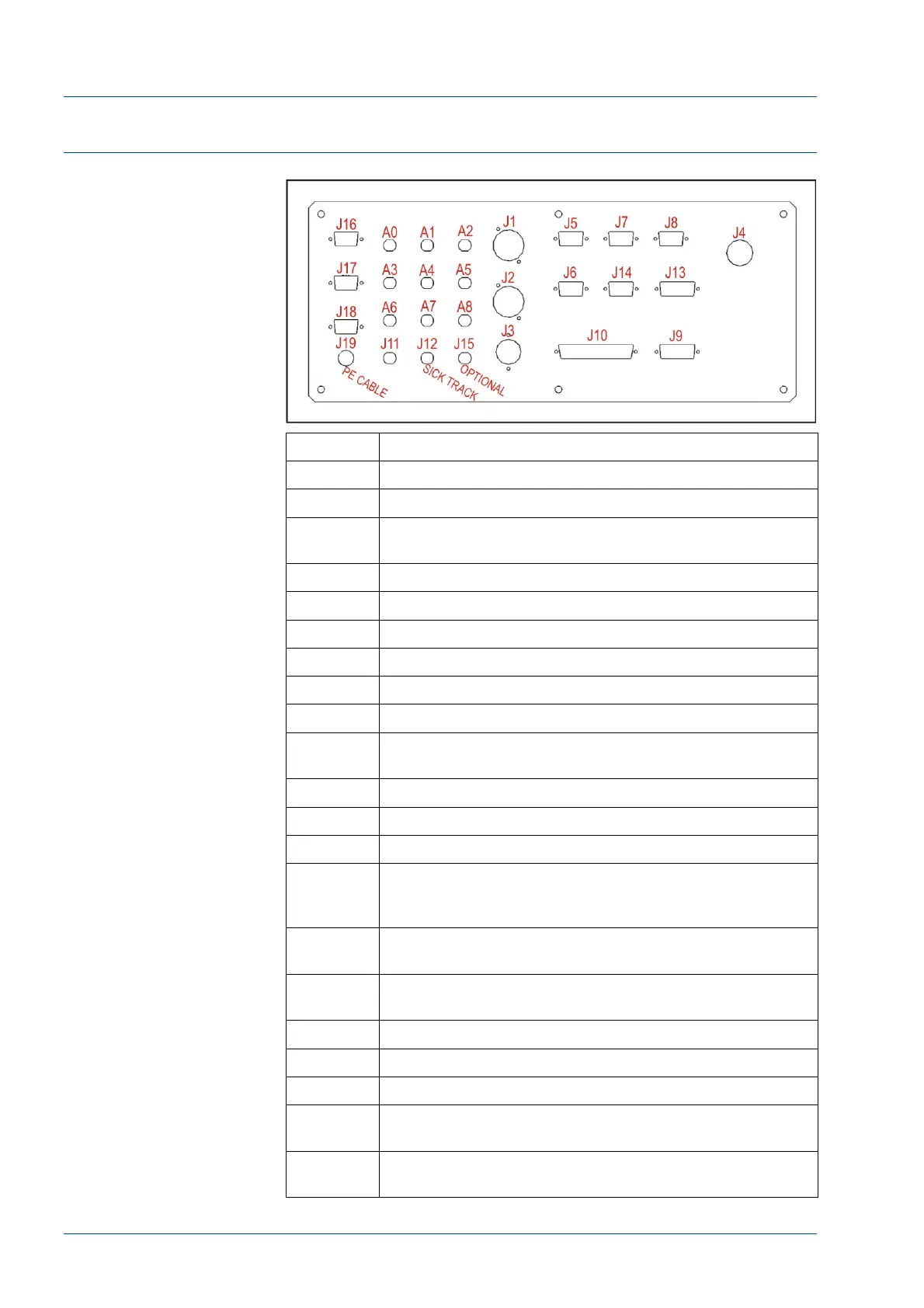
Electrical Panel Connectors
Figure 11 – Electrical Panel connectors
No. Description
A0 & A1 Track module antennas A0 and A1
A2 to A8 i2000SR IM antennas from A2 to A8
J1
i2000SR IM three Motors (Lane 1 & 2 motor, Lane 3 &
4 motor, and Disk motor)
J2 Instrument Indicator light (IM Status pole lamps)
J3 Track CAN bus power supply 24 V DC
J4 i2000SR 230 VAC power supply
J5 IM to Track CAN-BUS
J6 Future remote display/keyboard
J7 Track CAN bus SICK barcode
J8
LAS i2000SR Interface (Master tag reader RS-232 port
1) SCC Edgeport Port 4 (Com 6)
J9 Priority, Routine LEDs and Keypad
J10 Electro valves on pneumatic panel
J11 i2000SR IM power switch
J12
Carrier Detector (SICK optical sensor) detects that a
carrier was returned to track. Active track anti-
collision gate (G9)
J13
i2000SR IM G6 G7 G8 D3 Carrier Detector (SICK
optical sensor) gates
J14
Optional - To be used to program IM Track barcode
reader
J15 Not used, Optional
J16 Not Used
J17 Not Used
J18
i2000SR CLI Interface (Master tag reader RS-232 port
2) SCC Edgeport Port 1 (Com 3)
J19
+24 VDC return connected to i2000SR system
LLS/Process Path Ground.