Service Manual i2000SR interface module
625798100.APS.5.doc Page 33 of 212
In the Electrical box A3 and A4 antennas are connected to
MASTER CAN-BUS board.
A0, A1 and A2 antennas are connected to SLAVE 0 CAN-BUS
board.
A5, A6, A7 and A8 antennas are connected to SLAVE 1 CAN-BUS
board.
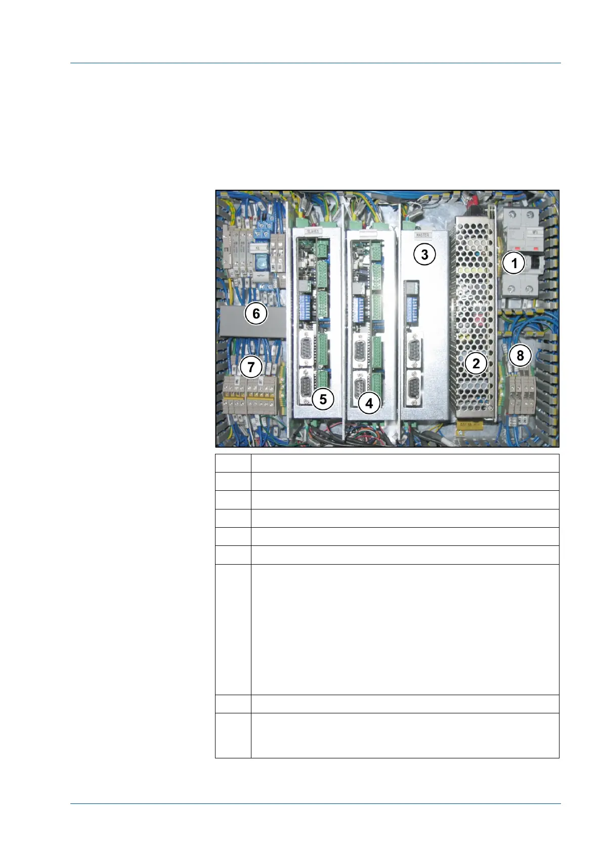
Figure 12 – i2000SR IM electrical box
No. Description
1 Main switch – Circuit breaker for power supply
2 Power supply +24/5 V DC (Note: 5 VDC is not used.)
3 Master Tag Reader Board
4 SLAVE 0 Tag Reader Board
5 SLAVE 1 Tag Reader Board
6 Relays & Connectors (Device control)
Relays:
K1 – Motors – Output bit 1 – Master pin 2
K2 – pole lamp Green – Output bit 2 – Master Pin 4
K3 – pole lamp Red – Output bit 3 – Master Pin 5
K4 – pole lamp Yellow – Output bit 4 – Slave 0 Expansion
Pin 2
Fuse:
F1: Main power fuse
7 Connectors (Power Distribution)
8 CAN-BUS line balancing diodes (D1 & D2)
Resistances to avoid current return (R1 & R2)
(added for IMQ conformance).