i2000SR interface module Service Manual
Page 60 of 212 625798100.APS.5.doc
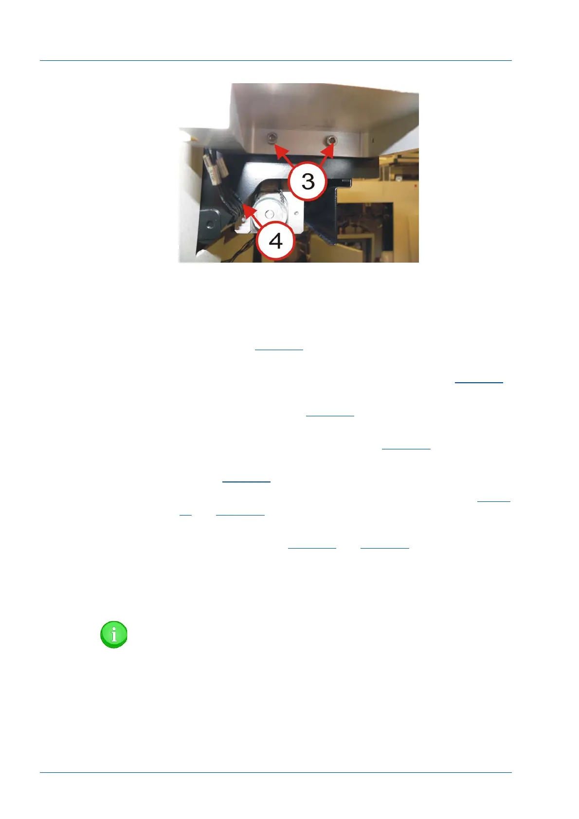
Figure 40 – 3 Button LUI Bracket
i2000SR / i2000SR IM Alignment Procedure
Alignment is acceptable when the following conditions have been
met:
• The support bracket feet do not touch a belt, tubing, or
cable. Refer to
Figure 49
.
• The difference between the left ends of the i2000SR and
i2000SR IM is 145 +/- 3 mm (5.75 +/- 0.125”). Refer to
Figure 44
.
• The support bracket alignment tabs are flush against the
IM rear surface. Refer to
Figure 42
.
• The tabs on the top surface of the IM are in the groove of
the tabs of the support bracket. Refer to
Figure 43
.
• The top surfaces of the IM and APS track belts are equal.
Refer to
Figure 39
.
• The IM and Workcell tracks must be level. Refer to
Figure
45
and
Figure 46
.
• The left/right and front/back planes of the i2000SR and the
IM are level. Refer to
Figure 47
and
Figure 48
.
• On-line carriers move from the workcell to and from the
IM without interference.
• Off-line carriers must move between all gate positions
without interference.
NOTE:
Adjust the height of the i2000SR by raising or lowering the
feet. To ensure the IM is being supported without applying
too must pressure, adjust the knurled knobs [1] on the
bracket as required.