Service Manual i2000SR interface module
625798100.APS.5.doc Page 61 of 212
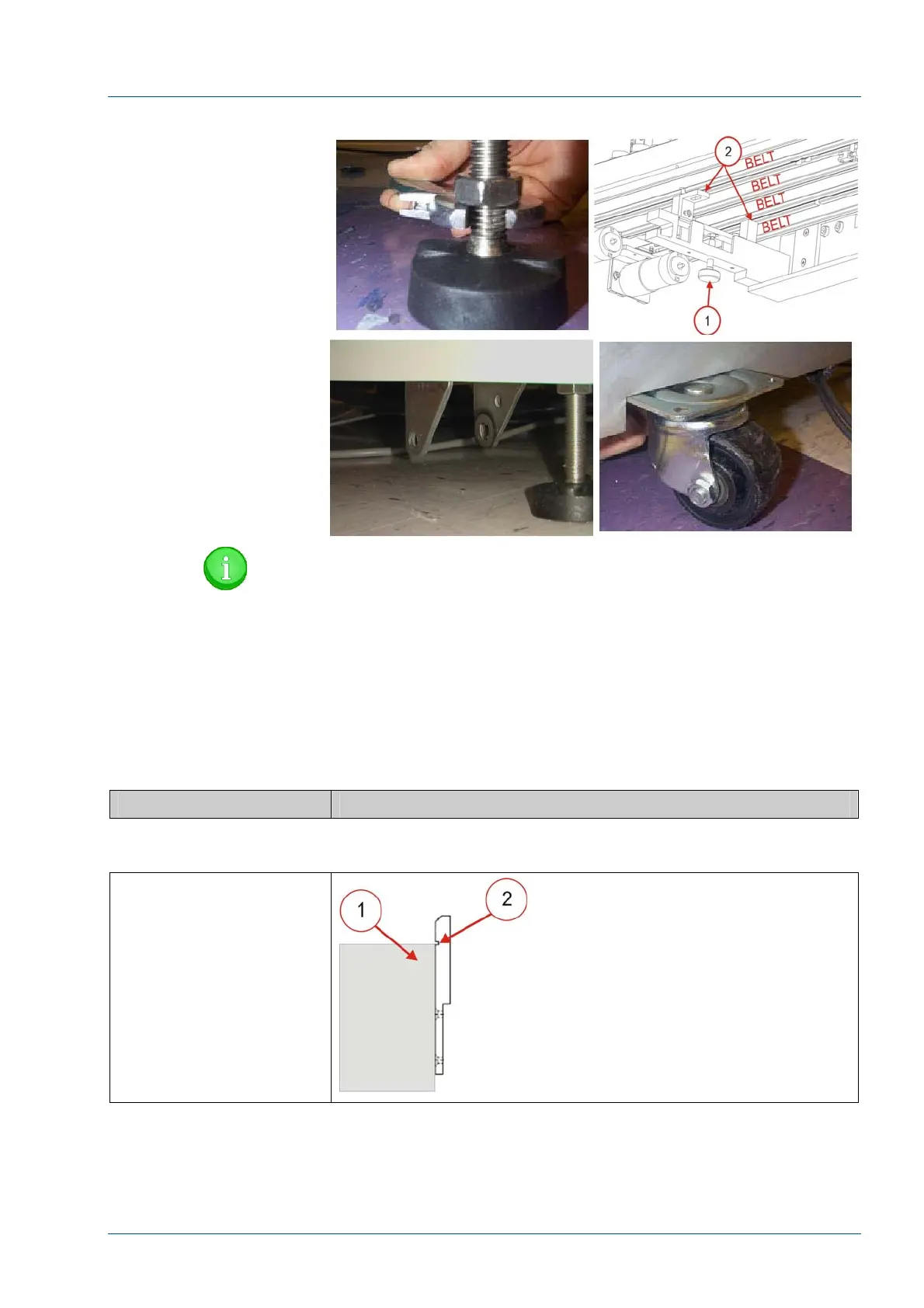
Figure 41 – i2000SR Height Adjustments
NOTE:
Because laboratory floor surfaces vary, it may necessary to
remove the wheels/casters to lower the i2000SR to the
height. For this procedure, refer to Architect i2000SR
service documentation.
• Adjust the i2000SR feet and support bracket knurled
knobs, as required, to position the i2000SR to meet the following
conditions:
Action Reference
Figure 42 – Support Bracket Reference Tabs
Support Bracket Tabs [2]
are flush against the side
of the IM track [1].
The IM track [1] is
positioned vertically so
that the track top surface
is within the groove on
the support bracket tabs
[2].