i2000SR interface module Service Manual
Page 64 of 212 625798100.APS.5.doc
Action Reference
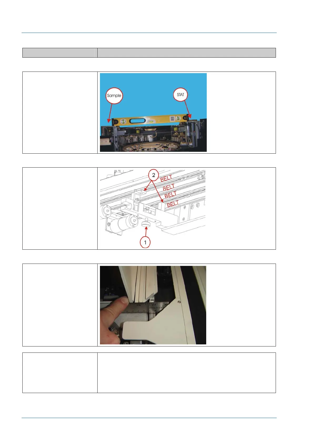
Figure 48 – Level i2000SR Left/Right
Place a level across the
top of the i2000SR
Sample and STAT pipettor
to indicate left to right
level of the i2000SR.
Adjust the feet as
required until the
i2000SR is level.
Figure 49 – Bracket Feet Clearance
The support bracket feet
do not pinch tubing or
cables and does not come
in contact with a belt.
Figure 50 – Belt surface difference
Confirm the surfaces of
Lane 1 and 4 belts are at
the same height as the
main track belt.
If it is not possible to
obtain a level condition,
loosen the five (5) bolts
used to attach the IM to
the workcell and adjust
the position of the IM.