Service Manual i2000SR interface module
625798100.APS.5.doc Page 87 of 212
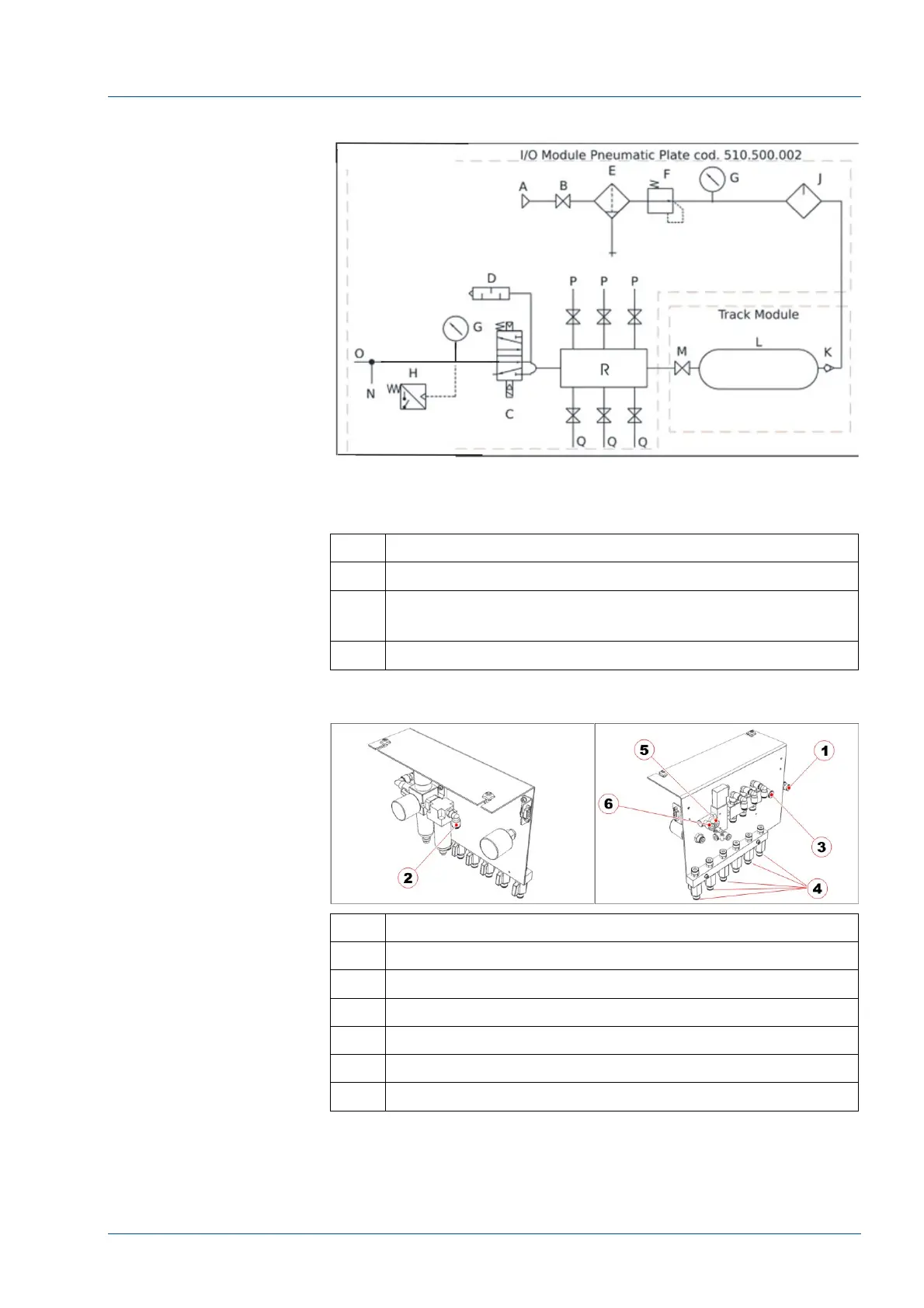
Figure 72 – Pneumatic Panel (New) P/N 510.500.002
No. Description
P i2000SR IMs (max 3)
Q I/O Storage (1)
Future modules (2)
R Pneumatic Manifold
Figure 73 – New pneumatic panel group
No. Description
1 Input 10 mm diameter pipe
2 Output 8 mm diameter pipe to the tank
3 Input 8 mm diameter pipe from the tank
4 Output 6mm diameter pipe to the i2000SR IMs and free
5 To the I/O Module 6 mm diameter pipe
6 To the Track Module 6 mm diameter pipe