i2000SR interface module Service Manual
Page 130 of 212 625798100.APS.5.doc
STEPS REFERENCES
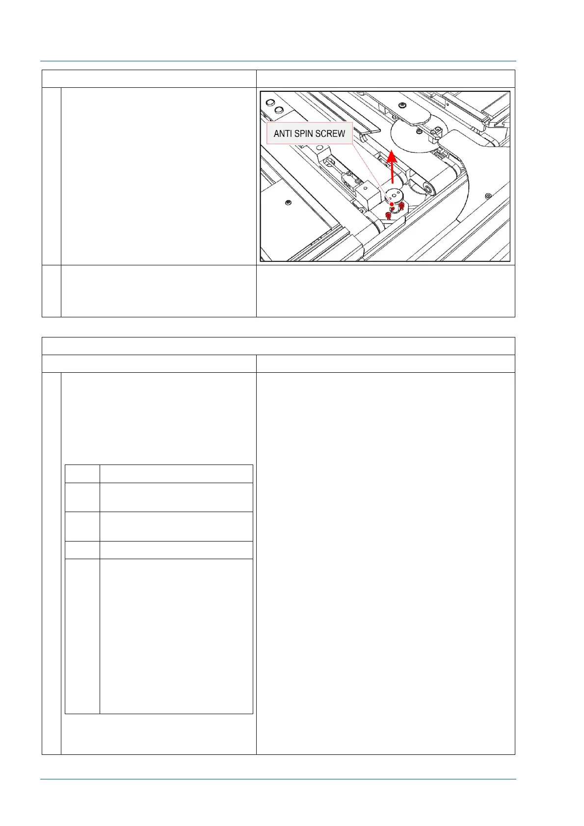
12 Loosen the shaft anti-spin screw. Be
careful because that screw was glued
to avoid loosening.
Remove the motor shaft.
Remove the two power wires from
motor connectors.
Finally loosen the two screws that
fasten the motor body to its support.
13 Replace the assembly and
reassemble by performing the above
steps in reverse order. Use Loctite to
secure the screws.
VERIFICATION
STEPS REFERENCES
1 With the i2000SR IM in the APS
position, restore power to the
workcell.
1. Turn i2000SR IM power switch
to APS position
2. Power on the Accelerator APS
UPS
No. Description
1 Bar Code Scanner beeps
once then twice.
2 Pole Instrument Indicator
Light turns RED
3 Tag Reader LEDs turn on
4 Pole RED lamp blinks until
the Master Slave to i2000SR
SCC communication check is
passed
1. SCC CLI Edgeport
port 1 (com 3)
2. Master Slave Port 2
(CLI)
3. SCC LAS Edgeport
port 4 (com 6)
4. Master Slave Port 1
(LAS)
NOTE:
The i2000SR IM will not initialize
unless the cable check is passed.
Refer to the “Accelerator APS Operations Manual –
SECTION 5 – Operating Instructions” to execute
the “Restoring Power after a Controlled Shutdown”
of the Workcell.