i2000SR interface module Service Manual
Page 152 of 212 625798100.APS.5.doc
STEPS REFERENCES
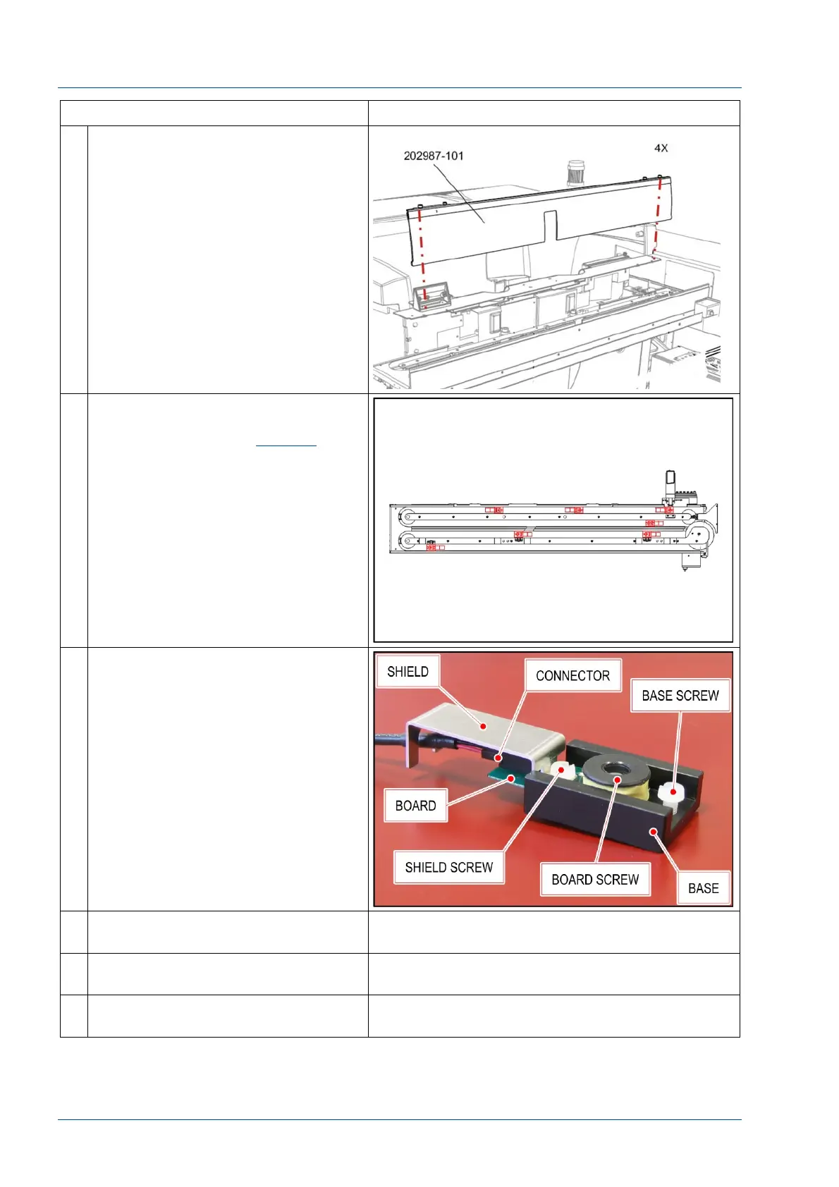
6 Remove the center cover by
loosening the four (4) ¼ turn screws.
7 i2000SR IM antenna locations are
shown in the figure. Track antenna
locations are shown in
Figure 6
.
The antenna can be accessed by
raising the appropriate belt.
To prevent interference from radio
frequencies, metal shields are used to
protect all i2000SR IM antenna
electrical connections.
8 Before removing the antenna coil,
trace the profile around the antenna
base using a pencil or other suitable
marker to mark its position. This
mark will be useful to quickly
reposition if the antenna base should
be moved during replacement.
NOTE:
The location of the antenna is very
critical. To prevent occurrence of
Sample Presentation errors, the
installed antenna needs to be
centered under the probe or stopped
carrier.
9 Unscrew shield screw to remove
shield.
10 Unscrew board screw to remove
antenna board and connector.
11 Install a new antenna board and
reassemble the board and shield.