5-5
5
2. Set the meter selector to the DC Voltage posi-
tion.
3. Connect the black tester lead to ground.
4. Using the red tester lead, contact each end of the
fuse holder connector terminals individually.
5. The meter must show battery voltage from one
side of the connector terminal ends.
NOTE: Battery voltage will be indicated from
only one side of the fuse holder connector termi-
nal; the other side will show no voltage.
NOTE: When testing the HI fuse holder, the head-
light OFF/HI/LO switch must be in the HI position;
when testing the LIGHTS fuse holder, the headlight
dimmer switch can be in either the HI or the LO
position.
NOTE: If the meter shows no battery voltage,
troubleshoot the battery, switches, power distribu-
tion module, or the main wiring harness.
Fuses
1. Set the meter selector to the OHMS position.
2. Connect the red tester lead to one spade end of
the fuse; then connect the black tester lead to the
other spade end.
3. The meter must show less than 1 ohm resis-
tance. If the meter shows open, replace the fuse.
NOTE: Make sure the fuses are returned to their
proper position according to amperage. Refer to
the amperage listed under each fuse on the power
distribution module.
Ignition Coil
The ignition coil is mounted on the fuel pump
mounting plate adjacent to the fuel pump.
VOLTAGE (Primary Side)
See PEAK VOLTAGE Primary/CDI in this sub-sec-
tion.
RESISTANCE
NOTE: For these tests, the meter selector should
be set to the OHMS position.
Primary Winding
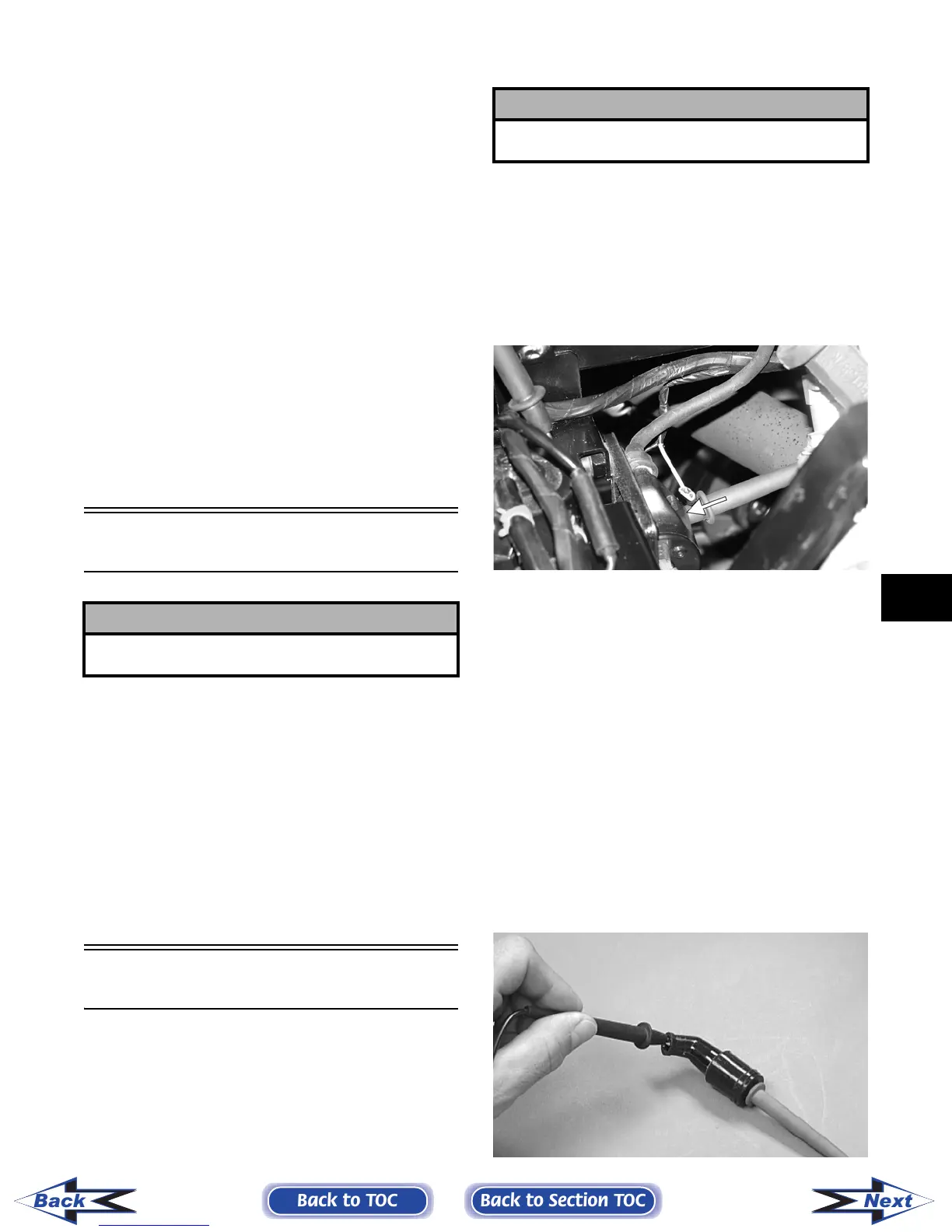
1. Connect the red tester lead to the terminal (with
the wire removed); then connect the black tester
lead to ground.
PR278A
2. The meter reading must be within specification.
Secondary Winding
1. Connect the red tester lead to the high tension
lead (with the plug cap removed); then connect
the black tester lead to ground.
2. The meter reading must be within specification.
NOTE: If the meter does not show as specified,
replace ignition coil.
Spark Plug Cap
1. Connect the red tester lead to one end of the cap;
then connect the black tester lead to the other
end of the cap.
AR603D
! CAUTION
Always disconnect the battery when performing
resistance tests to avoid damaging the multimeter.
! CAUTION
Always disconnect the battery when performing
resistance tests to avoid damaging the multimeter.
Back to TOC
Back to Section TOC
Next
Back
FOR ARCTIC CAT ATV DISCOUNT PARTS CALL 606-678-9623 OR 606-561-4983
www.mymowerparts.com