3-39
3
NOTE: Rotate the shafts back and forth to
ensure no binding or sticking occurs.
6. From the right side, install the remaining 8 mm
cap screws (two inside the case); then tighten
only until snug.
NOTE: Rotate the shafts back and forth to
ensure no binding or sticking occurs.
7. From the right side, install the case half 6 mm
cap screws; then tighten only until snug.
NOTE: Rotate the shafts back and forth to
ensure no binding or sticking occurs.
8. From the left side, install the 6 mm cap screws;
then tighten only until snug.
NOTE: Rotate the shafts back and forth to
ensure no binding or sticking occurs.
9. In a crisscross/case-to-case pattern, tighten the 8
mm cap screws (from steps 5-6) until the halves
are correctly joined; then tighten to specifica-
tions.
NOTE: Rotate the shafts back and forth to
ensure no binding or sticking occurs.
10. In a crisscross/case-to-case pattern, tighten the 6
mm cap screws (from steps 7-8) to specifica-
tions.
NOTE: Rotate the shafts back and forth to
ensure no binding or sticking occurs.
Installing Left-Side
Components
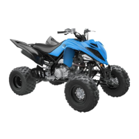
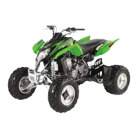
1. Install the shift indicator sending unit making
sure the two neutral contact pins and the two
springs are properly positioned. Tighten the
Allen-head screws securely.
CD997
CD994
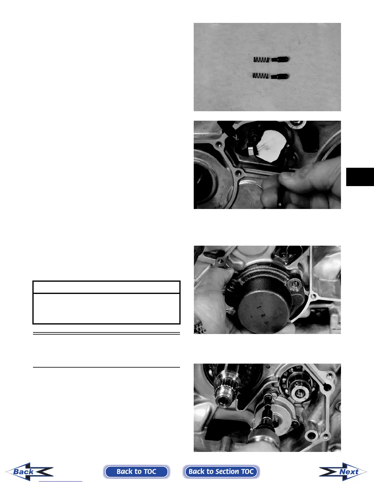
2. Install the secondary shaft bearing housing mak-
ing sure the two alignment pins are properly posi-
tioned. Tighten the Allen-head screws securely.
CD999
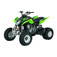
3. Install the oil pump onto the engine; then tighten
the Phillips-head screws securely.
CD988
AT THIS POINT
After completing center crankcase components,
proceed to Installing Left-Side Components, to
Installing Right-Side Components, and to Installing
Top-Side Components.
Back to TOC
Back to Section TOC
Next
Back
FOR ARCTIC CAT ATV DISCOUNT PARTS CALL 606-678-9623 OR 606-561-4983
www.mymowerparts.com