3-42
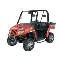
15. Spread the faces of the driven pulley by pushing
the inner face toward the engine while turning it
counterclockwise; then when the faces are sepa-
rated, insert a wedge (approximately 3/8 in.
thick) between the faces. Release the inner face.
16. Place the V-belt into position on the driven pul-
ley and over the front shaft.
PR389
NOTE: The arrows on the V-belt should point for-
ward.
17. Pinch the V-belt together near its center and
slide the spacer and movable drive face onto the
shaft. Secure the drive face with a nut (threads
coated with red Loctite #271). Tighten the nut to
specifications.
FI428A
NOTE: At this point, the wedge can be removed
from between the driven pulley faces.
18. Rotate the V-belt and drive/driven assemblies
until the V-belt is flush with the top of the driven
pulley.
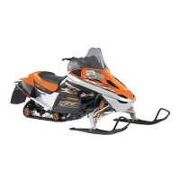
19. Place the V-belt cover gasket into position; then
install the cover and secure with the cap screws
making sure the different-lengthed cap screws
are in their proper location. Tighten the cap
screws to specifications.
CD083
Installing Right-Side
Components
NOTE: Plug the oil passage in the crankcase
housing prior to installing the drive gear/driven
gear assembly to prevent loss of an alignment pin.
1. Install the water pump driven gear alignment pin
and the driven gear (with the beveled side of the
gear facing outward as noted in removing); then
secure with the snap ring.
CD950A
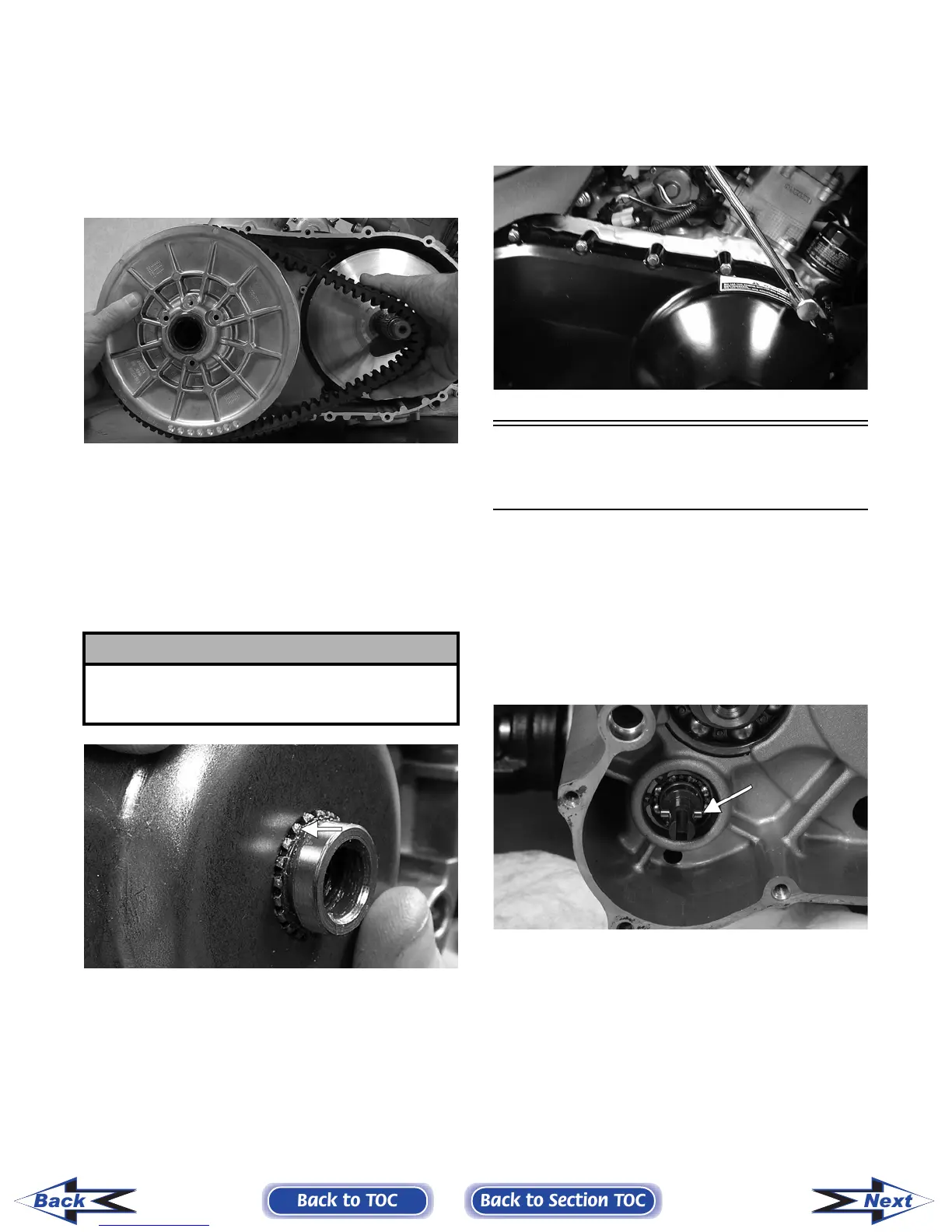
! CAUTION
Make sure the splines extend beyond the drive face
or a false torque reading and spline damage may
occur.
Back to TOC
Back to Section TOC
Next
Back
FOR ARCTIC CAT ATV DISCOUNT PARTS CALL 606-678-9623 OR 606-561-4983
www.mymowerparts.com