2-6
Valve/Tappet
Clearance
(Feeler Gauge Procedure)
To check and adjust valve/tappet clearance, use the
following procedure.
NOTE: The engine must be cold for this proce-
dure.
NOTE: The seats, center console, spark plug,
and air filter housing must be removed for this pro-
cedure.
1. Remove the timing inspection plug; then remove
the tappet covers (for more detailed information,
see Section 3 - Servicing Top-Side Components).
2. Rotate the crankshaft to the TDC position on the
compression stroke.
NOTE: At this point, the rocker arms and
adjuster screws must not have pressure on them.
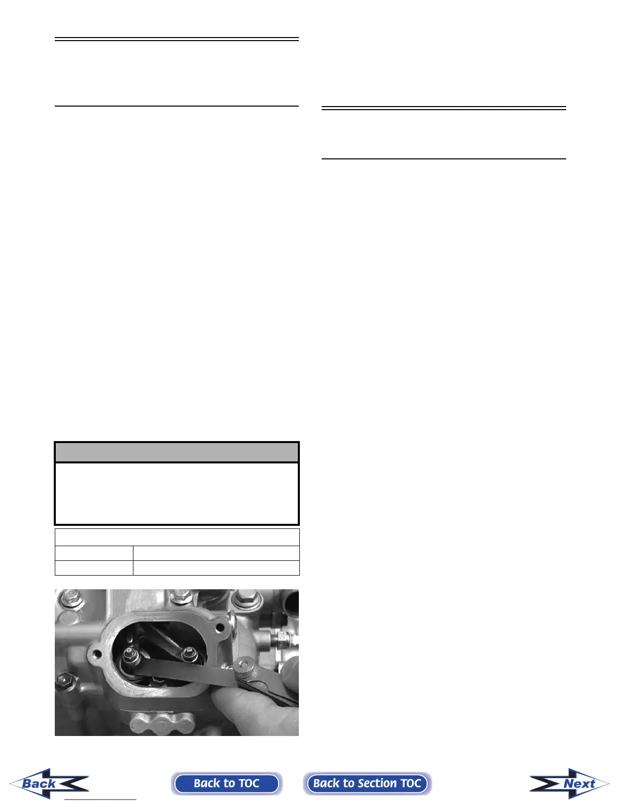
3. Using a feeler gauge, check each valve/tappet
clearance. If clearance is not within specifica-
tions, loosen the jam nut and rotate the tappet
adjuster screw until the clearance is within spec-
ifications. Tighten each jam nut securely after
completing the adjustment.
CC007D
4. Install the spark plug; then install the timing
inspection plug.
5. Place the two tappet covers with O-rings into
position. Tighten the cap screws securely.
Valve/Tappet Clearance
(Valve Adjuster Procedure)
To check and adjust valve/tappet clearance, use the
following procedure.
NOTE: The engine must be cold for this proce-
dure.
NOTE: The seats, center console, spark plug,
and air filter housing must be removed for this pro-
cedure.
1. Remove the timing inspection plug; then
remove the tappet covers (for more detailed
information, see Section 3 - Servicing Top-Side
Components).
2. Rotate the crankshaft to the TDC position on the
compression stroke.
NOTE: At this point, the rocker arms and
adjuster screws must not have pressure on them.
NOTE: Use Valve Clearance Adjuster (p/n
0444-078) for this procedure.
3. Place the valve adjuster onto the jam nut secur-
ing the tappet adjuster screw; then rotate the
valve adjuster dial clockwise until the end is
seated in the tappet adjuster screw.
4. While holding the valve adjuster dial in place,
use the valve adjuster handle and loosen the jam
nut; then rotate the tappet adjuster screw clock-
wise until friction is felt.
5. Align the valve adjuster handle with one of the
marks on the valve adjuster dial.
6. While holding the valve adjuster handle in
place, rotate the valve adjuster dial counter-
clockwise until proper valve/tappet clearance is
attained.
NOTE: Refer to the appropriate specifications in
Feeler Gauge Procedure sub-section for the proper
valve/tappet clearance.
NOTE: Rotating the valve adjuster dial counter-
clockwise will open the valve/tappet clearance by
0.05 mm (0.002 in.) per mark.
! CAUTION
The feeler gauge must be positioned at the same
angle as the valve and valve adjuster for an accurate
measurement of clearance. Failure to measure the
valve clearance accurately could cause valve com-
ponent damage.
VALVE/TAPPET CLEARANCE
Intake 0.1016 mm (0.004 in.)
Exhaust 0.1524 mm (0.006 in.)
Back to TOC
Back to Section TOC
Next
Back
FOR ARCTIC CAT ATV DISCOUNT PARTS CALL 606-678-9623 OR 606-561-4983
www.mymowerparts.com