5-6
2. The meter reading must be within specification.
NOTE: If the meter does not show as specified,
replace the spark plug cap.
PEAK VOLTAGE
NOTE: All of the peak voltage tests should be
made using the Fluke Model 73 Multimeter (p/n
0644-191) with Peak Voltage Reading Adapter (p/n
0644-307). If any other type of tester is used, read-
ings may vary due to internal circuitry.
NOTE: The battery must be at full charge for
these tests.
Primary/CDI
NOTE: The CDI is located beneath the driver’s
seat above the battery.
1. Set the meter selector to the DC Voltage posi-
tion; then disconnect the blue/white primary
wire from the coil.
2. Connect the red tester lead to the primary wire;
then connect the black tester lead to ground.
3. Turn the ignition switch to the ON position.
4. The meter must be within specification.
5. With the test leads still connected, crank the
engine with the electric starter.
6. The meter must show 300-450 DC volts.
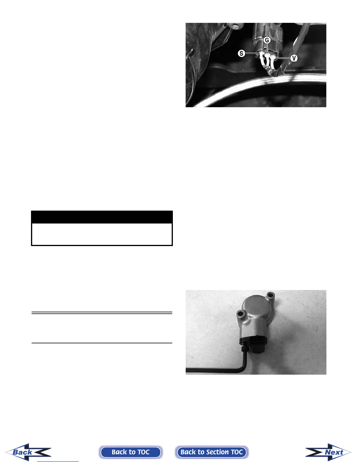
Speed Sensor
(XT)
NOTE: Prior to testing the speed sensor, inspect
the three-wire connector on the speed sensor for
contamination, broken pins, and/or corrosion.
1. Set the meter selector to the DC Voltage posi-
tion.
2. With appropriate needle adapters on the meter
leads, connect the red tester lead to the voltage
lead (V); then connect the black tester lead to
the ground lead (G).
PR279A
3. Turn the ignition switch to the ON position.
4. The meter must show approximately 6 DC volts.
5. Leave the black tester lead connected; then con-
nect the red tester lead to the signal lead pin (S).
6. Slowly move the vehicle forward or backward;
the meter must show 0 and approximately 6 DC
volts alternately.
NOTE: If the sensor tests are within specifica-
tions, the speedometer must be replaced (see Sec-
tion 9).
To replace a speed sensor, use the following proce-
dure.
1. Disconnect the three-wire connector from the
speed sensor harness or from the speed sensor;
then remove the Allen-head cap screw securing
the sensor to the sensor housing.
2. Remove the sensor from the sensor housing
accounting for an O-ring.
CD070
3. Install the new speed sensor into the housing
with new O-ring lightly coated with multi-pur-
pose grease; then secure the sensor with the
Allen-head cap screw (threads coated with blue
Loctite #242). Tighten securely.
! WARNING
Do not touch the primary wire with the ignition
switch turned on or severe electrical shock will
occur.
Back to TOC
Back to Section TOC
Next
Back
FOR ARCTIC CAT ATV DISCOUNT PARTS CALL 606-678-9623 OR 606-561-4983
www.mymowerparts.com