7-4
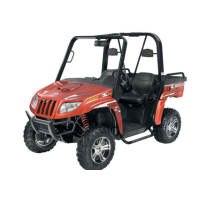
10. Remove the cap screws securing the A-arms to
the frame.
AF610D
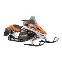
11. Remove the circlip from the ball joint; then
remove the ball joint from the A-arm.
AF616D
CLEANING AND INSPECTING
NOTE: Whenever a part is worn excessively,
cracked, or damaged in any way, replacement is
necessary.
1. Clean all A-arm components in parts-cleaning
solvent.
2. Clean the ball joint mounting hole of all residual
Loctite, grease, oil, or dirt for installing pur-
poses.
3. Inspect the A-arm for bends, cracks, and worn
bushings.
4. Inspect the ball joint mounting holes for cracks
or damage.
5. Inspect the frame mounts for signs of damage,
wear, or weldment damage.
INSTALLING
1. Apply green Loctite #609 to the entire outside
diameter of the ball joint; then install the ball
joint into the A-arm and secure with the circlip.
AF616D
2. Install the A-arm assemblies into the frame
mounts and secure with the cap screws. Only
finger-tighten at this time.
AF610D
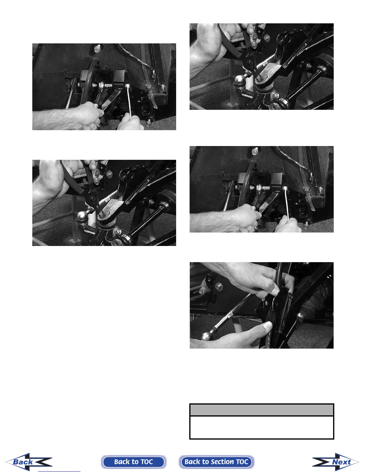
3. Route the brake hose through the upper A-arm
shock absorber mount.
AF627D
4. Secure the lower eyelet of the shock absorber to
the upper A-arm. Tighten nut to specifications.
5. Secure the A-arm assemblies to the frame
mounts (from step 2). Tighten the cap screws to
specifications.
! CAUTION
Do not tighten the nut beyond the 4.8 kg-m (35 ft-lb)
specification or the shock eyelet or mount WILL be
damaged.
Back to TOC
Back to Section TOC
Next
Back
FOR ARCTIC CAT ATV DISCOUNT PARTS CALL 606-678-9623 OR 606-561-4983
www.mymowerparts.com