3-19
3
CC668
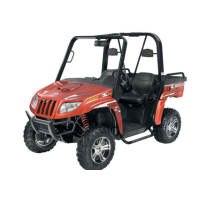
3. Remove the shift shaft (H); then remove the two
forks taking note of the direction of the tabs on
the forks for assembling purposes.
4. Remove the gear shift shaft (G) noting the loca-
tion of the two holes on the end of the shaft.
Account for two washers.
PR380A
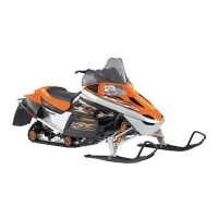
5. Remove the countershaft assembly (D). Account
for a washer on each end of the countershaft.
CC674
NOTE: Do not disassemble the countershaft
assembly unless necessary. If necessary, see Ser-
vicing Center Crankcase Components sub-sec-
tion.
6. Using a rubber mallet, tap on the crankcase to
remove the driveshaft (E).
CC675
7. Note the timing marks on the crank balancer
gear (B) and crankshaft gear (C) for assembling
purposes; then slide the crank balancer gear off
the crank balancer. Account for the key in the
keyway.
CD826
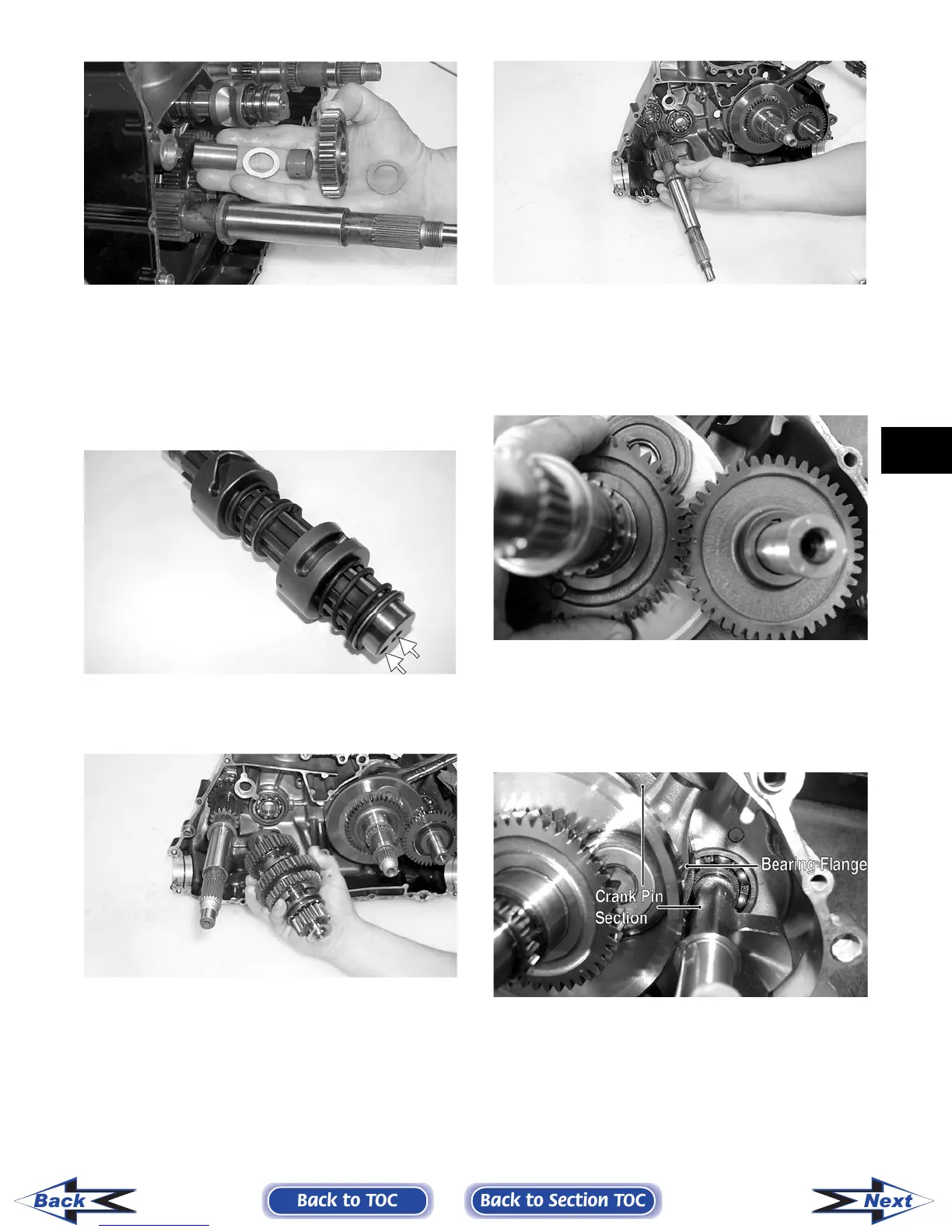
8. Remove the crank balancer.
NOTE: There is a flat spot on the crank balancer
bearing flange to allow clearance past the crank-
shaft.
CD832B
9. Remove the snap ring securing the water pump
driven gear shaft.
10. Using a hydraulic press, remove the crankshaft
assembly.
NOTE: Use a protective end cap to prevent dam-
age to the crankshaft threads.
Back to TOC
Back to Section TOC
Next
Back
FOR ARCTIC CAT ATV DISCOUNT PARTS CALL 606-678-9623 OR 606-561-4983
www.mymowerparts.com