should be mounted on the inner side of guide
frame direction).(see fig.4)
J Insert the starting relay into the inserter
preset by the rear fender, the direction should be
ensured the convenience of inserting.(see fig.4)
M After putting the vent pipe of battery
through the plastic clip mounted on the rear
fender, insert it into the hole preset by the rear
fender, (Combine with G)(see fig.4)(If free of
maintenance battery is used. then this item of
requirement doesn’t need).
U When assembling, mounting supporting
pad of vent-pipe shouldn’t be leaked, and pay
attention to let the direction of mark upward.
(see view D )
N In here, the wire of taillight must be put
through the slot hole preset by tool kit from the
bottom of tool kit.(see view F)
2.Technical requirement
¢ÙIn the drawing, the wiring condition and
position for all kinds of wires on the ATV body
is marked. When assembling the finished ATV,
wiring should be done as per the drawing in
principle.
¢ÚFor the wiring and fixing method which
can’t be marked in the drawing , necessary tech-
nical explanation has been made, you should abide
to execute in assembling.
¢ÛFor the place of using plastic clip stipu-
lated in the drawing, if can’t be used temporarily,
you can use band to fix it.
¢ÜThe dimension in the drawing is only used
for reference in operation, while not be used as
checking data. In the details of marking the code
No. of component, the self-carrying component
(wire etc.)of units only be marked with name.
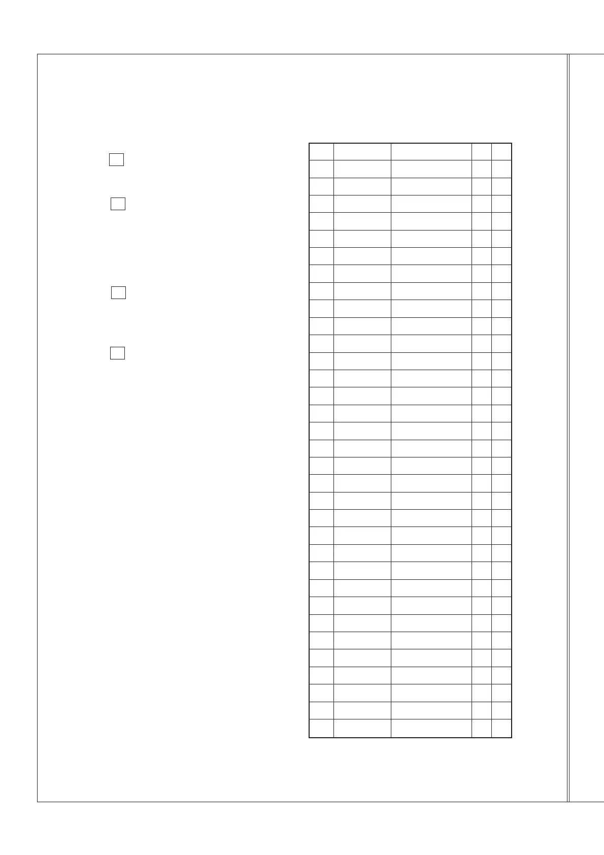
3.Details of relative component
- 17 -
Wire clip 4
Wire clip 3
Wire clip 2
Wire clip 1
Cable band
band of steering bar
C.D.I magneto wire
Vent-pipe of carburetor
Cut-off relay
Starting relay
Cable
Ven-pipe of rear brake
Wire of starting motor
High voltage coils and wire
Vent-pipe of battery
Vent-pipe of front
Wire of headlight
Rear brake cable
Wire of handle bar switch
Wire of clutch wire
Throttle cable
Front brake cable units
Wire of mileage meter
Wire of neutral switch
Wire of reverse switch
Overflowing hose of carburetor
Vent-pipe of gearbox
Taillight unit
C.D.I
Rectifier
Vent-pipe of gearbox
Main switch lock
Wire clip unit
Name
33
32
31
30
29
28
27
26
25
24
23
22
21
20
19
18
17
16
15
14
13
12
11
10
9
8
7
6
5
4
3
2
1
Ser.No.
SSA0-000512-0
SSA0-000511-0
SSA0-000510-0
SSA0-000509-0
150.00-0.39
150.00-03
150.00-06
FG-802000-0
SSA5-320000-0
SSA0-000516-0
SSA0-000515-0
SSA4-230000-0
SSA4-230000-0
SSA4-210000-0
SSA4-220000-0
SSA0-000517-0
SS45-630000-0
FG-803000-0
FG-805000-0
SSA5-510000-0
SSA0-012000-0
Code
3
2
3
2
6
2
1
1
1
1
1
1
1
1
1
1
1
1
1
1
1
1
1
1
1
1
1
1
1
1
1
1
1
Q’ty
Remark