23-3
PPC Manual Revision 1
Chapter 23: D Registers (Holding Registers)
23.2 Conventions Used in D Register Tables
This section describes the conventions used in the D register map tables.
Alphabet characters in the register map represent process data, operation parameters,
setup parameters, and other flag register names.
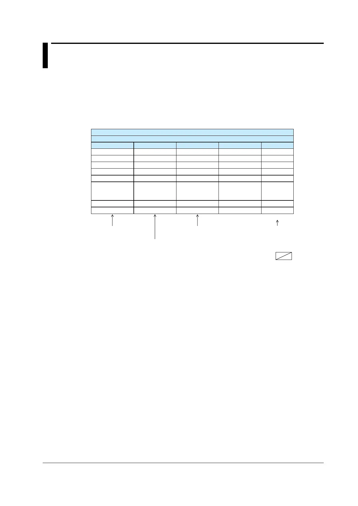
Register map (Categories)
Register contents
D-Reg No. Ref. No. H No. Register symbol R/W
D2001 42001 07D0
AD1.E
*1 R
D2002 42002 07D1
PV1.E_L1
*1 R
D2003 42003 07D2
PV_L1
*1 R
D2004 42004 07D3 CSP_L1 R
D2005 42005 07D4 OUT_L1 R
•
•
•
•
•
•
•
•
•
•
•
•
•
•
•
numbers
numbers (for Modbus
Read/writee by communication
R: Read enabled
W: Write enabled
: No register
*1: Register symbols listed in blue-color boldface (e.g.,
AD1.E
PPC5.
D Register Symbols
• With regards to some D register symbols, the loop number, terminal area, and
symbols.
If both the loop number and group number are added to the parameter symbols,
they are added in the order of _loop number and _group number.
oooo
_Ln_Y
Ln
Y
oooo
_En
En
oooo
_Sn
Sn
Example :
SP_L1_3
Indicates Loop-1 SP of group 3.
A2_2
Indicates A2 of group 2.

 Loading...

