23-8
PPC Manual Revision 1
Chapter 23: D Registers (Holding Registers)
Process Data Area
Some of the D registers represent multiple events such as errors and status depending
on combinations of bits in the register.
In the following tables, if an event indicated by a specific bit occurs, the state of that bit
changes to “1.”
If no event occurs, the state of that bit is “0.” Blank lines in each table indicate unused
bits.
Process Data (D2001 to D2100)
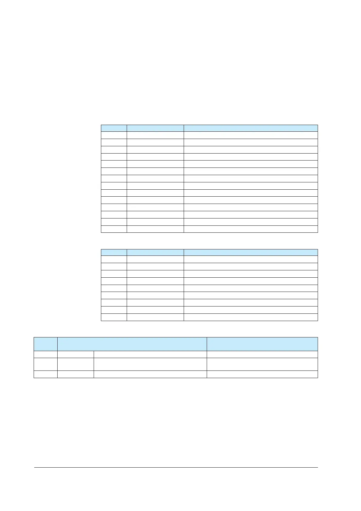
Bit Configuration of D2001: AD1.E (A/D converter error status 1)
Bit Symbol Event
0 ADERR PV input A/D converter error
1 ADERR_E1
2
3
4
5 RJCERR PV input RJC error
6
7
8 ADBO PV input burnout error
9 ADBO_E1
10
11
12
13 to 15
Bit Configuration of D2002: PV1.E_L1 (Loop-1 PV input error status)
Bit Symbol Event
0 PVBO_L1 Loop-1 PV input burnout error
1 RSPBO_L1 Loop-1 RSP input burnout error
2
3
4 PVPOVER_L1 Loop-1 PV input over-scale
5 PVMOVER_L1 Loop-1 PV input under-scale
6 to 13
14 ATERR_L1 Loop-1 auto-tuning timeout error
15
D2003 to D2007
Register
No.
Description Range and meaning of value
D2003
PV_L1
Loop-1 measurment value
D2004 CSP_L1 Loop-1 control setpoint
D2005 OUT_L1 Loop-1 control output -5.0 to 105.0%

 Loading...

