23-72
PPC Manual Revision 1
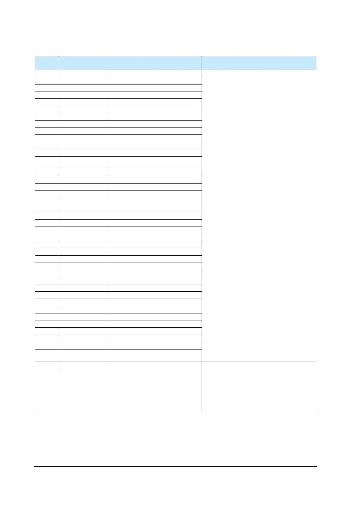
Chapter 23: D Registers (Holding Registers)
DI Function Setting (D5901 to D6200)
Register
No.
Description Range and meaning of value
D5901
A/M-D
*1
AUTO/MAN switch
Set an I relay number of contact input.
Standard terminals
DI1: 5025, DI2: 5026, DI3: 5027
E1-terminal area
DI16: 5046
D5902
R/L_L1-D
*1
REMOTE/LOCAL switch
D5903
R/L_L2-D
*1
REMOTE/LOCAL switch
D5904
S/R-D
*1
STOP/RUN switch
D5905
CAS-D
*1
Switch to CAS
D5906
AUTO-D
*1
Switch to AUTO
D5907
MAN-D
*1
Switch to MAN
D5908
REM_L1-D
*1
Switch to REMOTE
D5909
LCL_L1-D
*1
Switch to LOCAL
D5910
REM_L2-D
*1
Switch to REMOTE
D5911
LCL_L2-D
*1
Switch to LOCAL
D5912
D5913
HOLD-D
*1
Switch to HOLD (Start of hold-mode
D5914
AT-D
*1
Auto-tuning START/STOP switch
D5915
TRK-D
*1
Output tracking switch
D5916
SW-D
*1
PV switch
D5917
PVHD-D
*1
PV hold
D5918
CTOA-D
*1
CAS to AUTO switch
D5919
D5920
LAT-D
*1
Latch release
D5921
LCD-D
*1
LCD backlight ON/OFF switch
D5922
MG1-D
*1
Message display interruption 1
D5923
MG2-D
*1
Message display interruption 2
D5924
MG3-D
*1
Message display interruption 3
D5925
MG4-D
*1
Message display interruption 4
D5926
PRG-D
*1
D5927
RST-D
*1
D5928
LOC-D
*1
D5929
REM-D
*1
D5930
P/R-D
*1
PROG/RESET switch
D5931
P/L-D
*1
D5932
WAIT-D
*1
Wait ON/OFF switch
D5933
A/M_L1-D
*1
AUTO/MAN switch
D5934
A/M_L2-D
*1
Loop-2 AUTO/MAN switch
D5935
L/C-D
*1
D5936
P/H-D
*1
PROG/HOLD switch
D5937
PVRW_L1-D
*1
Loop-1
PV red/white switch
D5938
PVRW_L2-D
*1
Loop-2
PV red/white switch
D5939
S.HLD-D
*1
Switch to HOLD for synchronized program
operation
D5940 to D5940
D5941
SP.BC
Bit changing method of SP number
0: Status switch 1
(Operation by key keystrokes or via
communication is enabled according to the
1: Status switch 2
(Operation by key keystrokes or via
*1:
Same parameter exists in other menu. “-D” is added to the end of the parameter in DI.SL menu.

 Loading...

