1-15
PPC Manual Revision 1
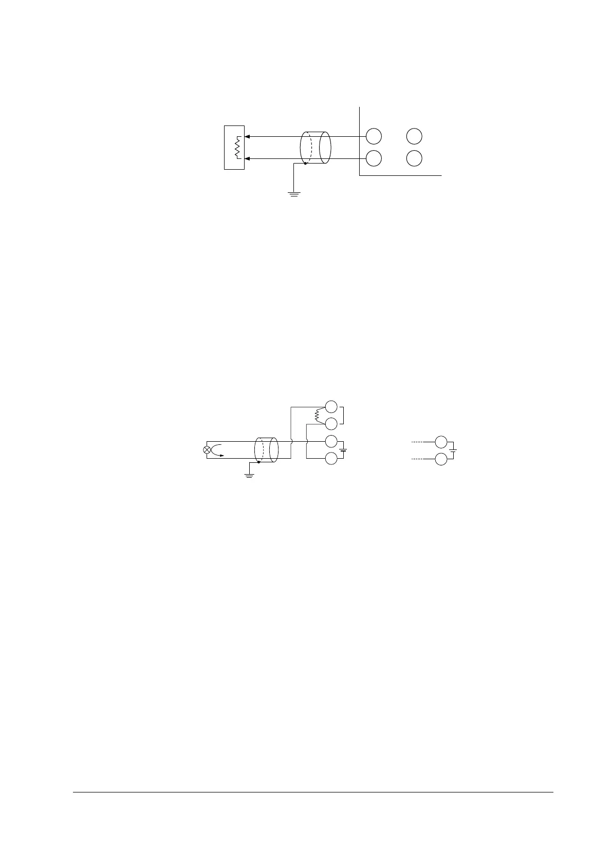
1.4.7 Retransmission Output Wiring
206
205
208
207
Grounding
OUT
terminals
RET
terminals
Shield
–
+
Receiver
(Recorder etc.)
Receiving resistor:
600 Ω or less
1.4.8 15 V DC Loop Power Supply Wiring
PV input
Shield
–
+
RET terminals
14.5-18.0 V DC
RL*
206
205
203
202
4-20 mA DC
*Resistor RL is not required if PV input is configured
for current input. If 2-wire transmitter cannot drive
into the controller’s 250 ohm PV input impedance
when configured for current, configure PV input for
voltage input and use a resistor, RL, sized according
to the requirements of the 2-wire transmitter that is used.
OUT terminals
14.5-18.0 V DC
208
207
or
Chapter 1: Installation and Wiring

 Loading...

