About this product
20 AVENTICS | Marex 3D | R417003094–BDL–001–AA
A standard Marex 3D system comprises
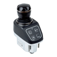
W Joystick Type 531
W 3D Controller
W Heading sensor
W CAN cabling and adapters
In applications with Marex OS III, one CAN bus line is connected
to the control units of Marex OS III (Cross CAN bus). A second
CAN bus line provides the communication from the joysticks to
the 3D Controller (Joystick CAN bus). Additionally, one NMEA
2000 bus cable is connected between the 3D Controller and the
heading sensor (NMEA 2000 bus).
In applications with Marex ECS, the 3D Controller is connected
to the STATION bus line between Marex ECS control unit and the
first control head. The connection of joysticks and the heading
sensor is identical to applications with Marex OS III.
The following figures show the system setup with Marex OS III
and Marex ECS.
2 Number of CAN bus connector
3 Type of connector (male/female)
3D_manual_R417003094_DE_EN.book Seite 20 Freitag, 30. November 2018 11:36 11