Installation
44 AVENTICS | Marex 3D | R417003094–BDL–001–AA
O When using the cables No. R419801568 or R419801522, cut
the connector and attach the wires directly to terminals 1
and 4.
Only use the option with the dual battery cable, if both
voltage sources have the same potential. The negative
terminals of both voltage sources must be bridged
(common ground).
5.3.2 Connecting Marex OS III and Marex ECS
Observe the maximum cable length from the first to the last bus
participant when installing the components.
The maximum length of the Joystick + Cross CAN bus is
300 m.
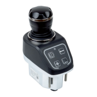
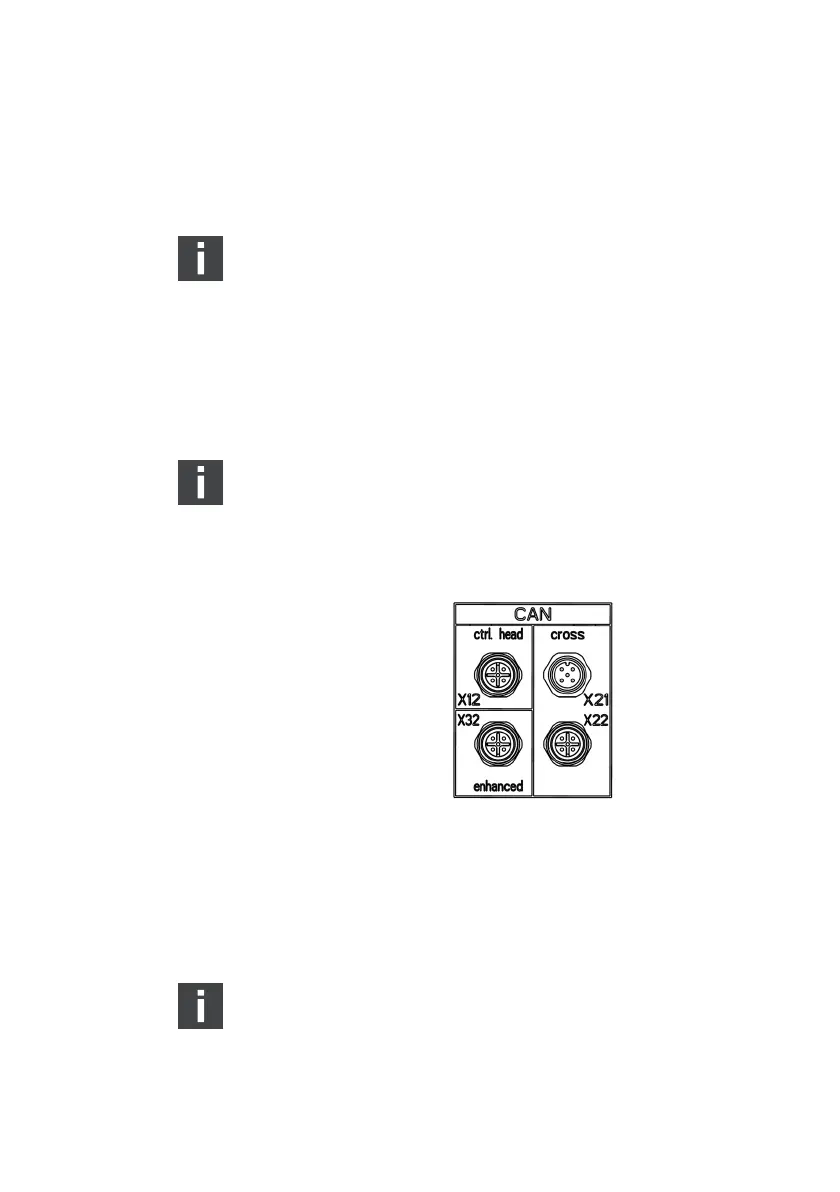
1. At the front of the housing, 4 CAN bus connections type M12
are provided (fig. 17). Remove the protective caps which
cover the data bus connections.
Fig. 17: 3D Controller, M12 CAN bus connectors
2. Connect the bus cables according to the following diagrams
and by observing your project documentation. Make sure the
connections are secure and tight. Observe the maximum
cable lengths indicated in the connection diagrams.
Unused CAN bus connectors must be covered by a
protective cap.
3D_manual_R417003094_DE_EN.book Seite 44 Freitag, 30. November 2018 11:36 11