Installation
50 AVENTICS | Marex 3D | R417003094–BDL–001–AA
Accessories, on page 92. Observe the maximum cable length of
the NMEA 2000 bus of 200m.
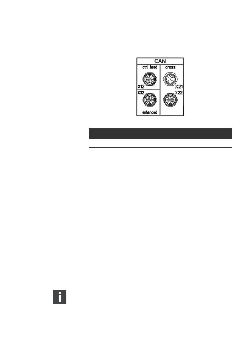
Fig. 25: CAN bus connectors at the 3D CONTROLLER
Proceed as follows:
O Remove the protective cap from connector X32 at the front
of the 3D controller.
O Connect the cable R419801829 to the connector X32 at the
3D CONTROLLER.
O Plug in the other end of the the cable R419801829 into the
corresponding socket at the bottom of the heading sensor.
The heading sensor is now ready for operation.
5.3.5 Connecting the thrusters
The connection of thrusters to the 3D Controller varies
depending on type and brand of thruster. This chapter shows
the connections for the most frequent thruster types.
Thrusters from CMC and BCS as well as On/Off thrusters must
be hardwired to the terminals of the 3D Controller.
O Apply the cable glands for hardwired connections to the
3D Controller.
Side Power thrusters equipped with S-Link gateway can be
connected via NMEA2000-bus at connector X32 of the 3D
controller. The S-Link gateway is not part of the scope of
supply of Aventics. Additionally, an S-Link interface cable is
required which must be ordered separately. (See also
chapter 9, Accessories on page 92).
Bus cable M12 connector Connect to
NMEA 2000 X32 (ENHANCED), socket GPS and Heading Sensor
3D_manual_R417003094_DE_EN.book Seite 50 Freitag, 30. November 2018 11:36 11