Installation
AVENTICS | Marex 3D | R417003094–BDL–001–AA 47
English
setup and symbols, on page 19, as well as chapter 9,
Accessories on page 92.
In applications with Marex OS III single engine systems, the
default setting of the dip switches must be changed. The dip
switch S2 must be set to "on".
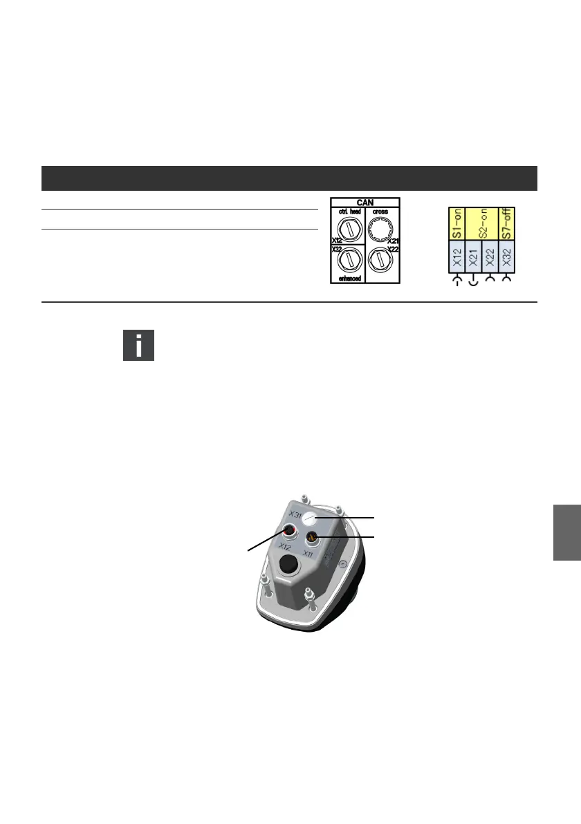
5.3.3 Connecting the Joystick
5.3.3.1 Connectors
At the bottom of the joystick, two round M12 connectors are
provided for the connection to the Marex 3D controller and other
joysticks.
Fig. 21: Electrical connectors
Proceed as follows to connect the joystick:
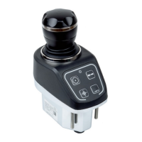
Table 2: Default setting of CAN termination at the 3D Controller
Dip switch CAN bus Default setting CAN connectors Symbols
S1 Joystick CAN bus X12 ON
S2 Cross CAN bus, X21, X22 OFF
S7 NMEA 2000 bus, X32 ON
1
X11 M12, 5 pins, male Connection for the 3D controller
and joystick
2
X12 M12, 5 pins, female Connection for the joystick
3
X31 not assigned
3D_manual_R417003094_DE_EN.book Seite 47 Freitag, 30. November 2018 11:36 11