Installation
46 AVENTICS | Marex 3D | R417003094–BDL–001–AA
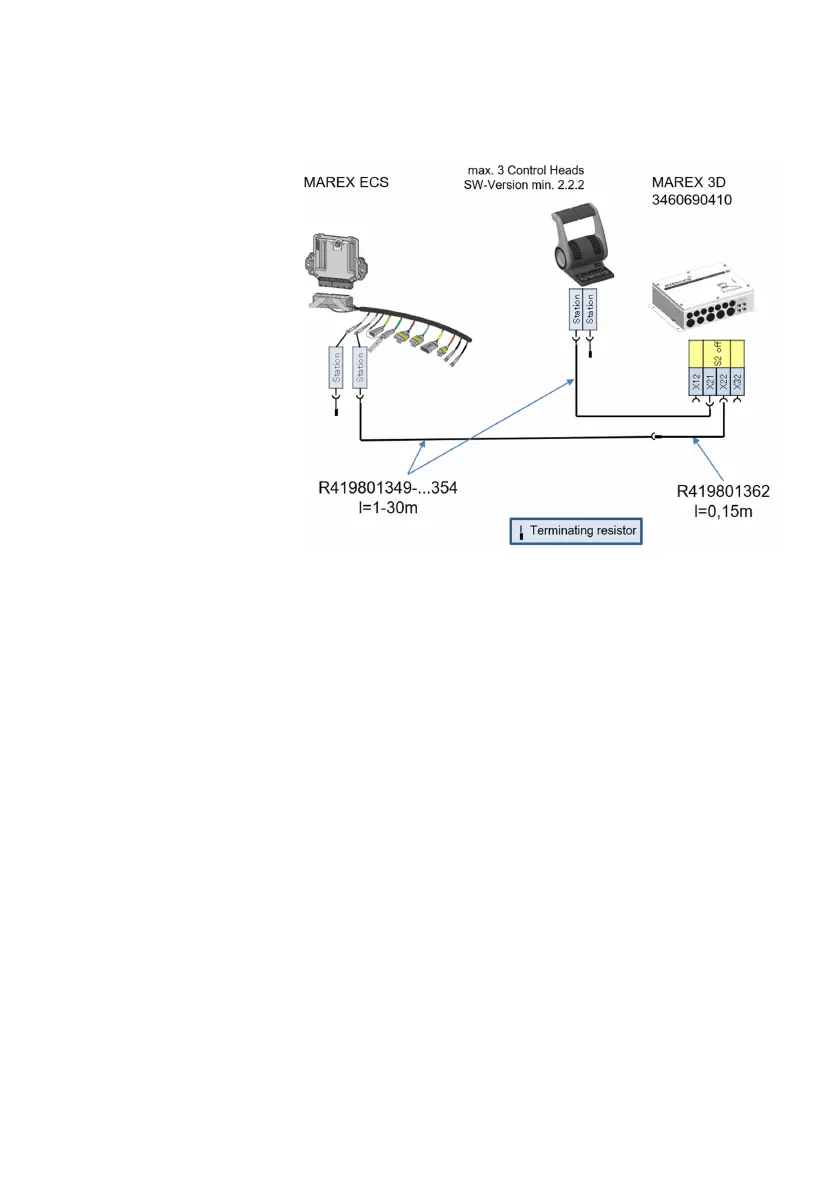
Fig. 20: Connection diagram for Marex ECS
5.3.2.1 Data bus termination
A terminating resistor must be applied at both ends of each CAN
or NMEA 2000 bus line. The 3D Controller provides terminating
resistors for one end of every bus line. The terminating resistors
can be switched on or off using dip switch elements at the
electronic board of the 3D Controller. Depending on the setup of
your Marex 3D system, it can be required to adjust the settings
of the terminating resistors in the 3D Controller.
O Refer to chapter chapter 4.3.2.3, Dip switch elements, on
page 34 for general information on the terminating resistors
at the 3D Controller.
O To view and access the dip switches, remove the cover of
the 3D Controller. See also fig. 12, 3D Controller, cover with
fastening screws on page 40.
O Use a small screw driver when adjusting the dip switch
elements.
O Make sure that both elements of the dip switch are set in the
same position.
O Apply terminating resistors also at the other end of each
CAN or NMEA 2000 bus line. See also chapter 4.2.1, System
3D_manual_R417003094_DE_EN.book Seite 46 Freitag, 30. November 2018 11:36 11