About this product
34 AVENTICS | Marex 3D | R417003094–BDL–001–AA
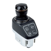
4.3.2.3 Dip switch elements
The electronic board of the 3D Controller is equipped with
several dip switches each of which provides 2 switch elements.
The dip switches S1, S2 and S7 are used to activate or
deactivate the terminating resistors of the CAN and NMEA 2000
bus outputs. The assignment of the dip switches and their
default setting are shown in table 2 on page 47.
In order to check or change the adjustment of the dip switches
the cover of the 3D Controller must be opened.
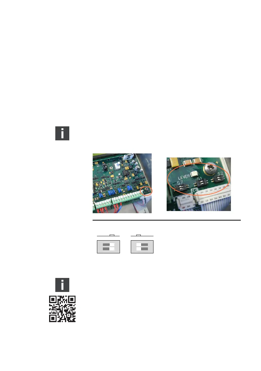
Both elements of the dip switch must be placed in the same
position. (See also fig. 6).
Fig. 6: Dip switch positions
Contact marineservice@aventics.com for further
information on the 3D Controller.
3D_manual_R417003094_DE_EN.book Seite 34 Freitag, 30. November 2018 11:36 11