Installation
48 AVENTICS | Marex 3D | R417003094–BDL–001–AA
1. Make sure that all components are dead before connecting
the joystick.
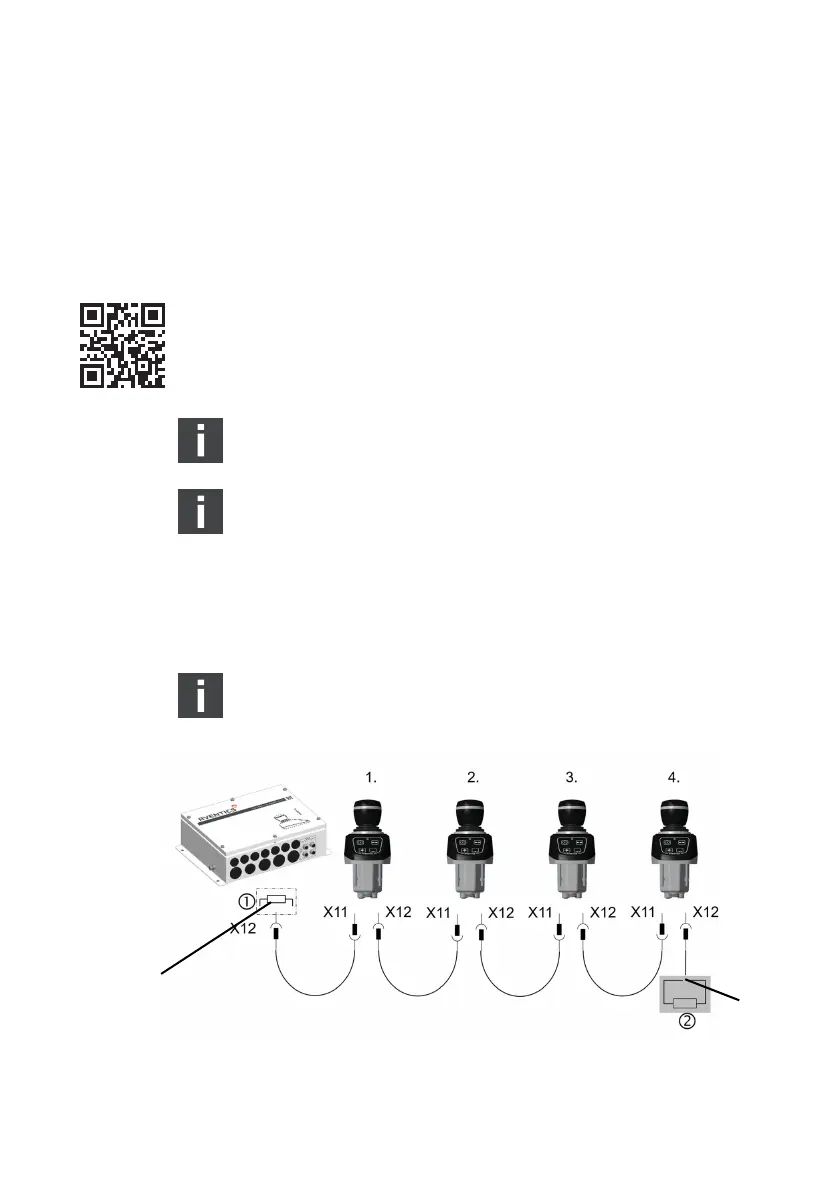
2. Use the connector X12 at the Marex 3D CONTROLLER to
connect a CAN bus cable M12. Route the other end of the
cable to Joystick Type 531 and connect it to connector X11
from underneath the control panel (fig. 22).
3. To connect another joystick, apply another CAN bus cable to
the connector X12 at the joystick. Route the cable to the next
joystick and connect it to X11. Proceed accordingly to
connect more joysticks if applicable.
Contact marineservice@aventics.com if you wish to
connect more than 4 joysticks to the 3D controller.
The maximum cable length from the 3D controller to the
last joystick is 300 m.
4. Apply a torque of 0.4 Nm to fasten the M12 connectors.
5. If no further joysticks are being installed, apply a
terminating resistor (AVENTICS material No. 8941054264)
to X12 at the last joystick.
There is no need to connect a terminating resistor to the
Marex 3D controller as one is already included in the device.
Fig. 22: CAN bus connection Marex 3D controller to Joystick Type 531
1 Terminating resistor in the 3D Controller
2 Terminating resistor, material No. 8941054264
3D_manual_R417003094_DE_EN.book Seite 48 Freitag, 30. November 2018 11:36 11