Installation
52 AVENTICS | Marex 3D | R417003094–BDL–001–AA
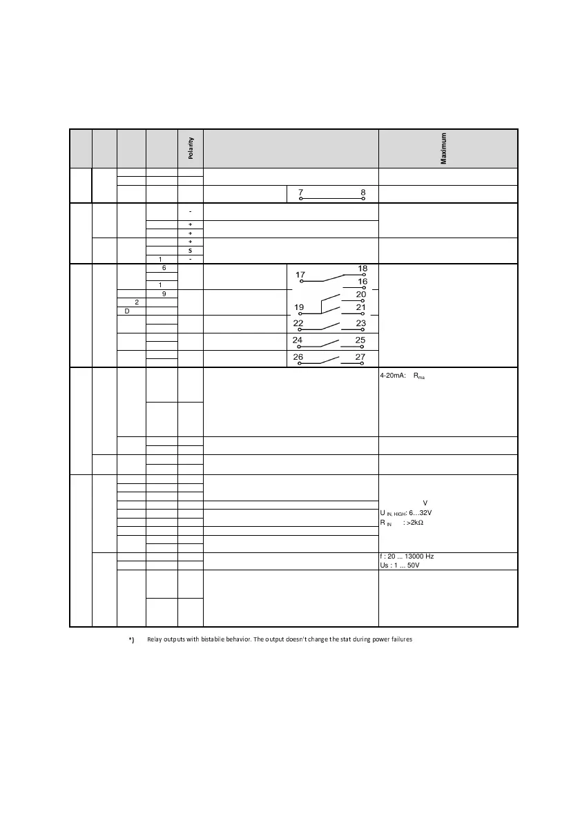
Fig. 27: Terminal connection table
Block
Function
Channel
no.
Terminal
Maximum
ratings
1, 2, 3
+
-
7, 8
terminals for unrestricted
use
9, 12
10
11
13
14
15
16
17
18
19
DO2 20
DO3 21
22
23
24
25
26
27
28
+
29
-
30
+
-
+
+
+
-
+
+
-
+
-
+
-
43
+
46
-
! " # # $
U
IN, LOW
: 0…2V
U
IN, HIGH
: 6…32V
R
IN
: >2kΩ
f : 20 ... 13000 Hz
Us : 1 ... 50V
4-20mA: R
max
: 500Ω
resolution: 12 Bit
0-10 V: I
max
: 20 mA (short-circuit proof)
resolution: 12 Bit
PWM: U
max
: 40 V (short-circult proof)
f: 100…1000 Hz
resolution 10 Bit
4-20 mA: R
max
: 500
Ω
resolution: 12 Bit
f = 20…13000 Hz
U
s
= 1 to 50 V
analogue output 4-20mA
frequency input
X9
Digital InputsPickup
digital inputs
common terminal (Di1, DI2, DI3)
relay output with bistabile
behavior
relay output
in case of resistive load and inductive load
with L/R <= 7ms (only with recovery diode)
switching voltage:: 32V DC
Max. current on contact: 2A DC
Min. current on contact: 10mA DC
X8
Outputs
Input
AI2
analogue output 4-20mA / 0-10V / PWM
potentiometer feedback for DC actuators
X7
Outputs
DO1
rela
out
ut for an external
alarm system
relay outputs with bistabile
behavior
X6
proportional valve:
12 / 24 V (3A), 50…20000 Hz
DC actuator:
12 / 24 V (3,5A), 50…20000 Hz
AO1 *)
AI1 *)
OutputInputs
terminnals for current measurement for proportional
valve A (9) and B (12) - mandatory
terminals for proportional valve A (10) and B (11) or for
DC actuator (10, 11)
power supply for pick-up at AI 3
The output can be used only at 24V supply voltage.
U
AO4,a
: 5... 12V (in 0,5V steps)
U
AO4,b
: 2... 10V (continnous)
I
max
: 50mA ((short-circuit proof)
U
B
- U
AO4
must be greater than 4,8V
frequency input
AO4 *)
digital input
digital inputs
common terminal (Di4, DI5)
DI6
AO3
DO6 relay output
AO2
DO4
DO5
24V DC -25%/+30%
12V DC -20%/+30%
Detailed
Function
supply voltage
X5
Power
supply
3D_manual_R417003094_DE_EN.book Seite 52 Freitag, 30. November 2018 11:36 11