5: Show Proles • 93
©2008 Axia Audio — Rev. 3.0
Master Module Control Lock Map
Element is a pretty powerful console — perhaps the
most powerful and flexible your jocks have ever used.
And that means that there are probably plenty of func-
tions you’d rather they not have access to; things that
could mess them up and result in the dreaded midnight
phone call.
The Master Module Control Lock Map allows you to
disable access to many Element functions to prevent set-
tings from being tampered with. This can be done on a
per-show basis, so remember that if you wish to disable
access to a certain function globally, you must do so in
every Show Profile.
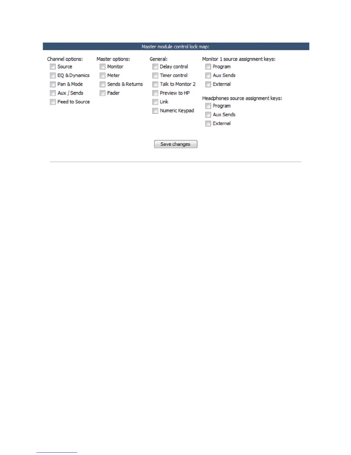
The screenshot in Figure 5-3 shows the wide range of
options you can lock down. This includes EQ and voice
dynamics, mix-minus settings, even things like Monitor
and Headphone assignments (for particularly clueless
members of the airstaff).
Placing a checkmark in any of these boxes means
that the operator will not be able to modify the settings
for that item which you’ve pre-loaded in the Show Pro-
file.
Save and Exit
Save Changes button applies any changes made to
the Auxiliary Send Description and returns you to
the Show Profile Settings menu.
•
Back to Show Prole link takes you back to Show
Profile Settings without saving changes.
Record Mode Screen
Element’s Record Mode helps talent quickly prepare
to record a phone bit, interview or other program seg-
ment for later air. Any source assigned to the Program-
4 bus automatically feeds the Record and Phone buses
as well. Sources assigned to Program-4/Record will
follow the Record options in their Source Profiles; the
CR Monitor assignment automatically changes to PGM-
4, and the bus assignment keys for channels assigned to
Program-4 will flash when Record Mode is active..
Record Mode Conguration
Record Mode Activation: If Disabled is chosen,
the board op will not be able to use Record Mode
while this Show Profile is loaded. Choose Enabled
to allow Record Mode to be used.
GPIO Channel for Recorder Control: Enter the
channel number of the GPIO port assigned to your
chosen recording device. This device will auto-
matically begin recording with the board op presses
Element’s Recode Mode Engage key. See Chapter
Three, “Configuring GPIO,” for a complete reference
of Element GPIO functions.
•
•
•
Figure 5-3: Master Module Control Lock Map. Keep those pesky jocks clamped down tight!